¶ Tools and Materials
- A 1.5 mm Allen key
- A 2.0 mm Allen key
- A 2.5 mm Allen key
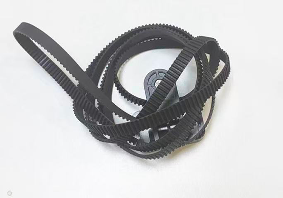
- A new timing belt
¶ Tutorial Video
Coming soon.
¶ Instruction
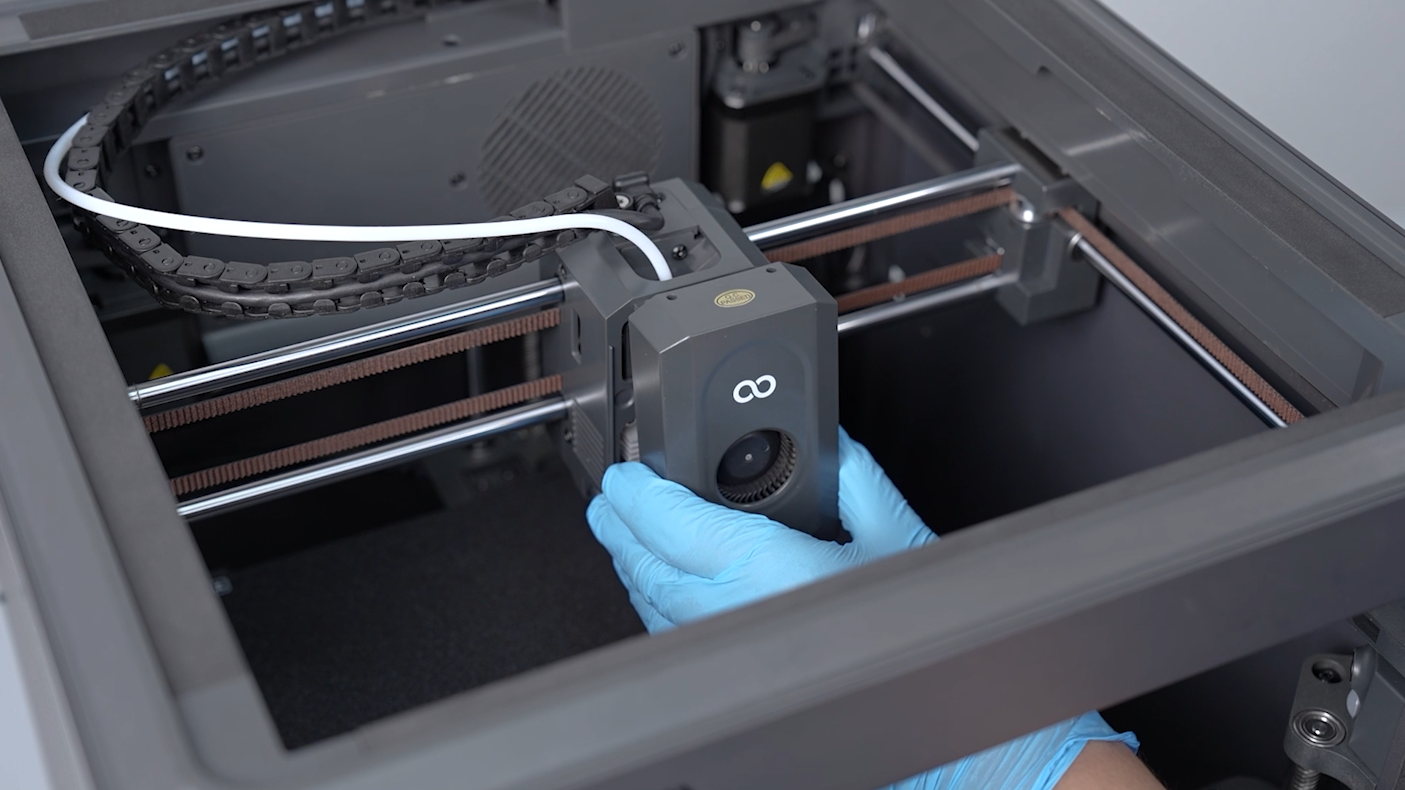
¶ Remove the print head assembly
- Power off the printer and unplug the power cord.
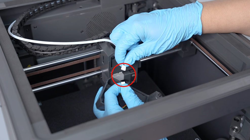
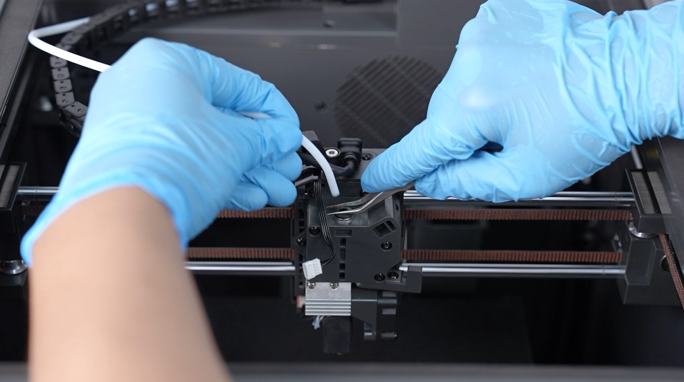
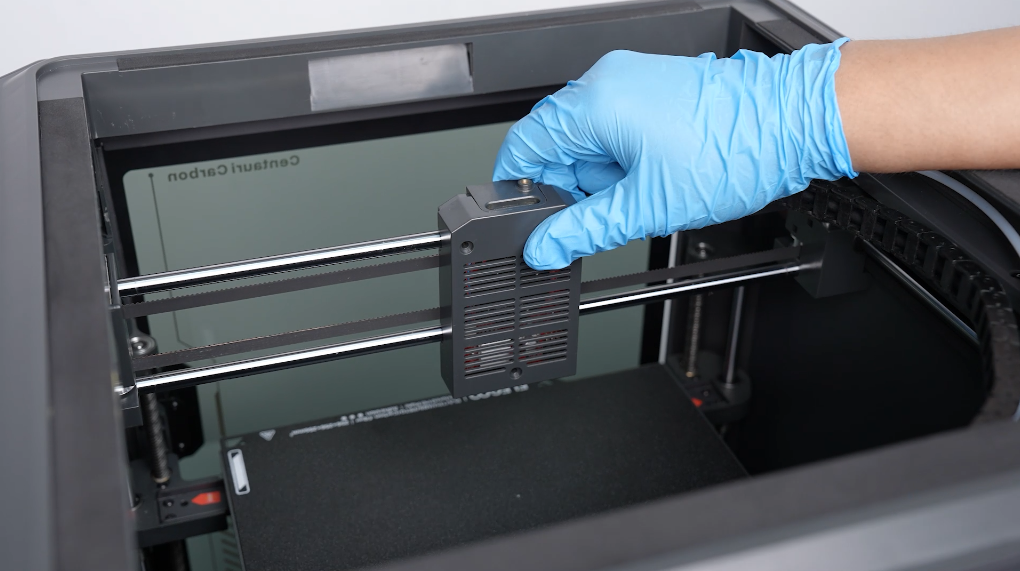
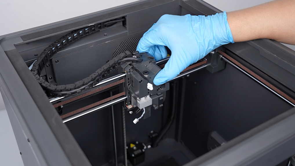
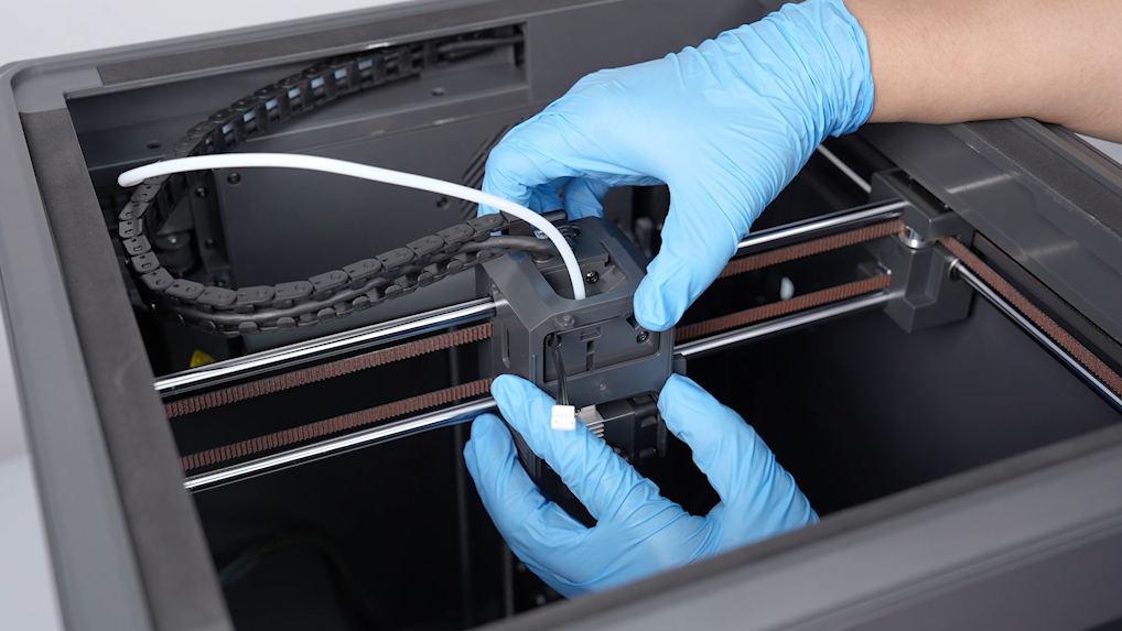
- Lift the front cover of the print head and remove it. Unplug the port of the ribbon cables of the model cooling fan.
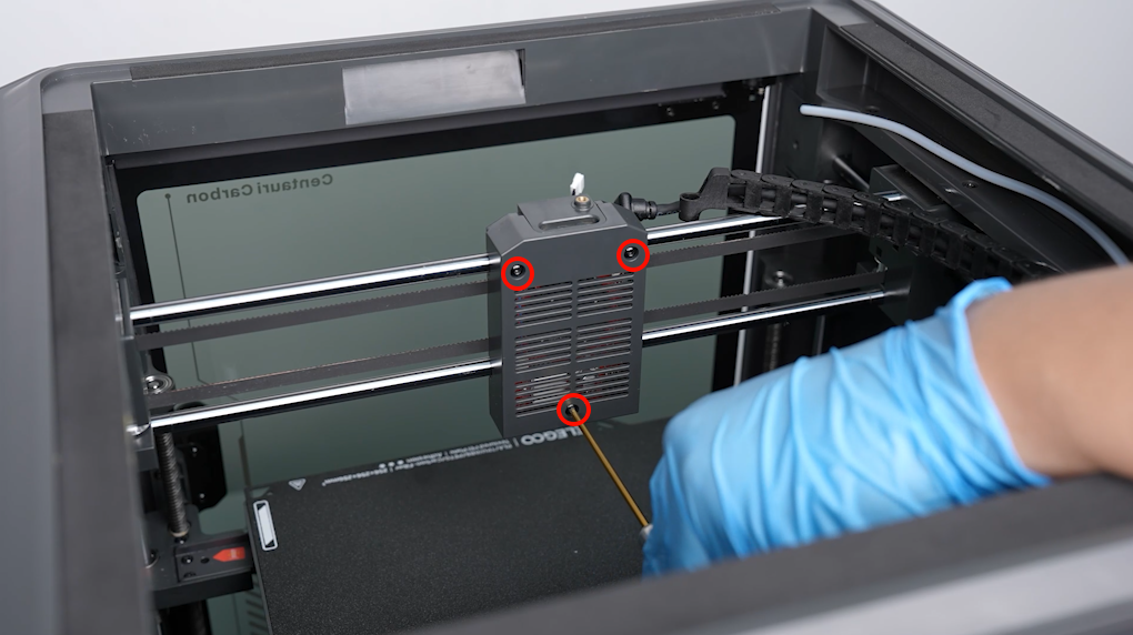
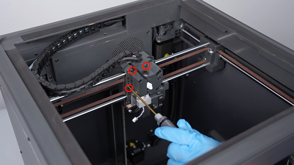
- Loosen the 4 screws securing the middle housing of the print head using a 2.0 mm Allen key. Remove the middle housing from the front of the print head.
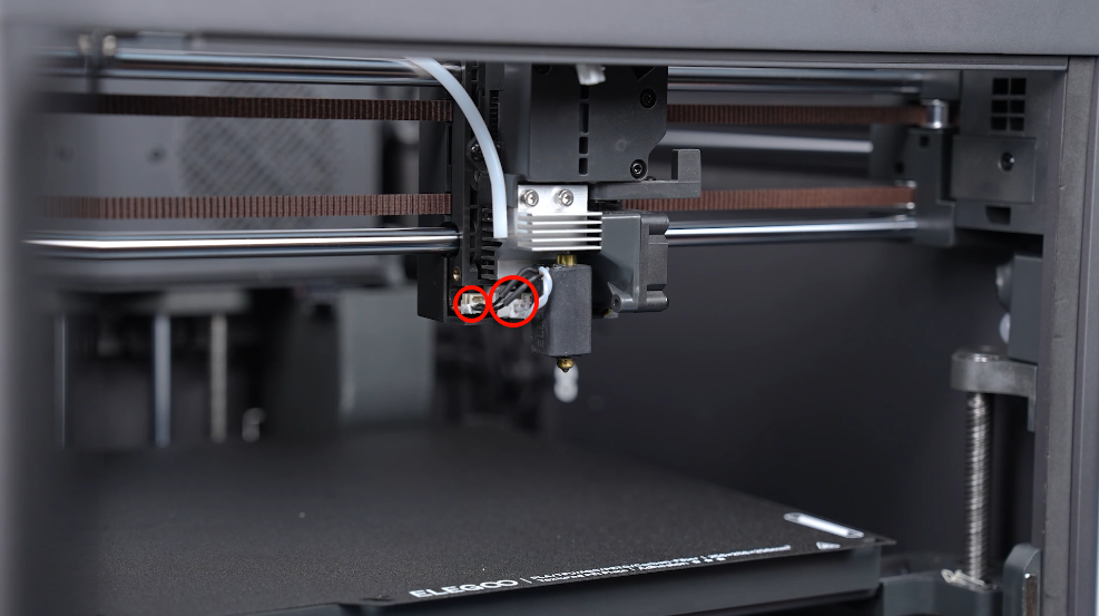
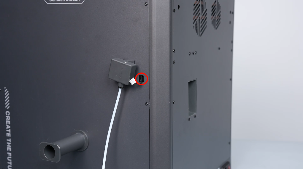
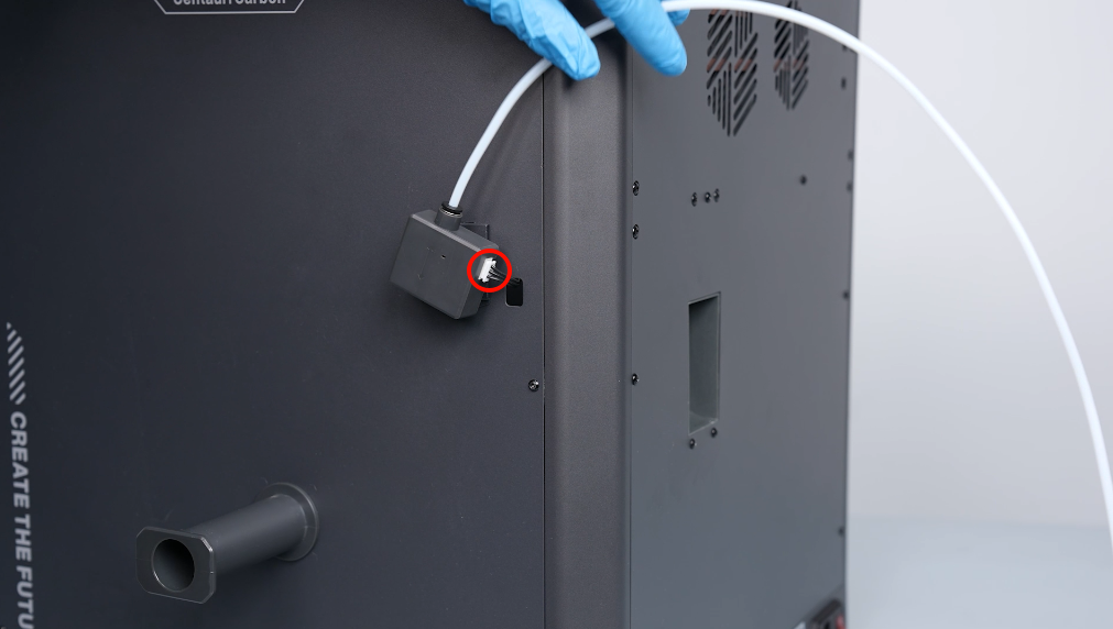
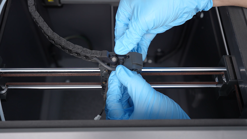
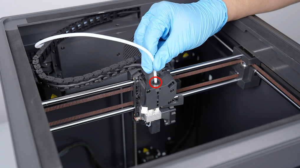
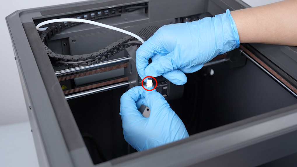
- Press downward the tablet of the connector using a pair of tweezers, then unplug the PTFE tube. Disconnect ribbon cables of the ceramic heating plate and the thermistor.
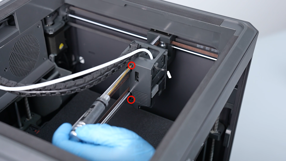
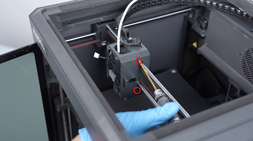
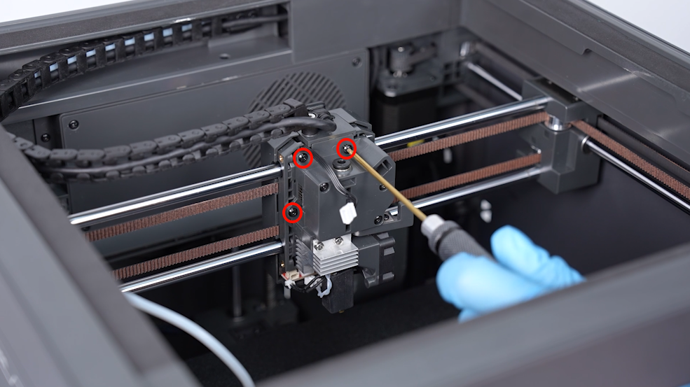
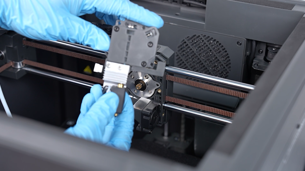
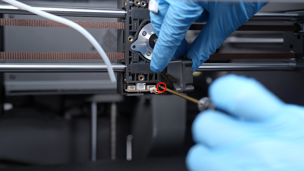
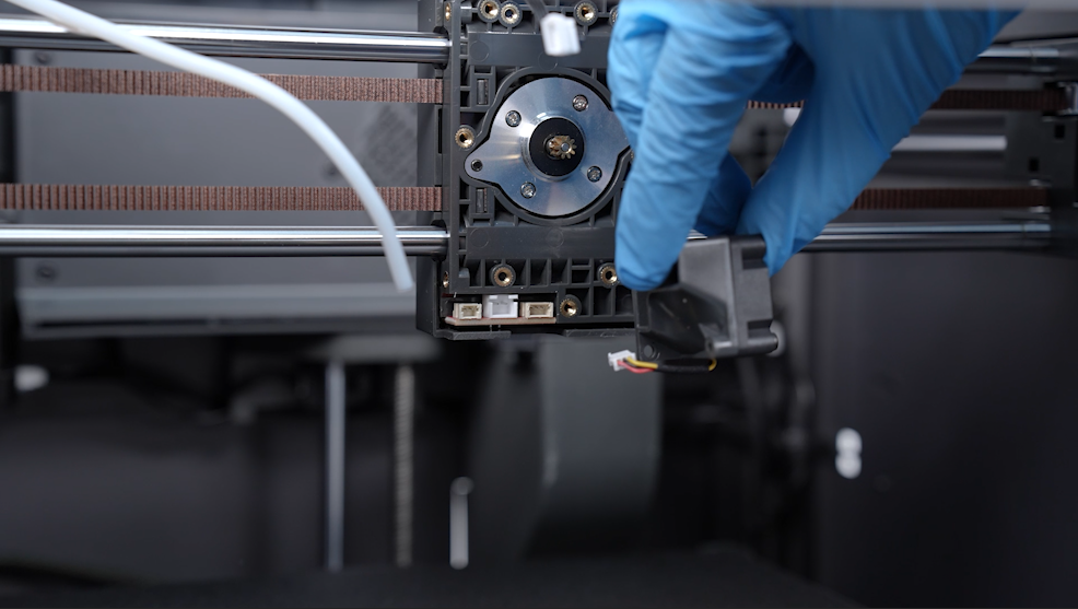
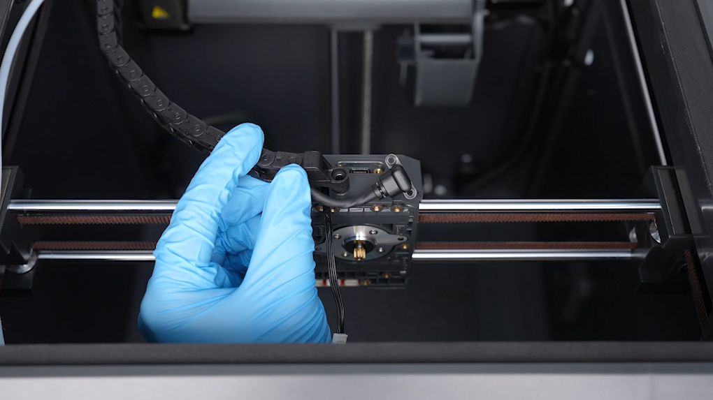
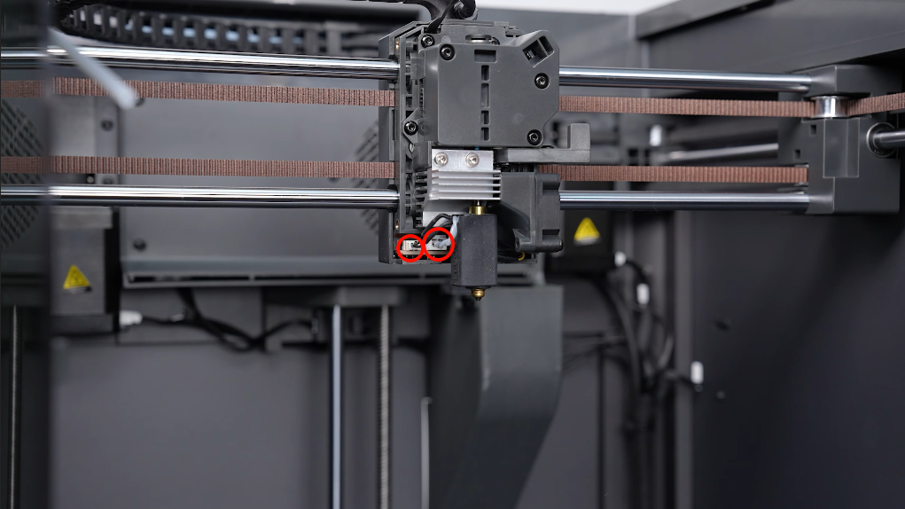
- Loosen the 4 screws securing the gear box assembly of the extruder using a 2.0 mm Allen key. Remove the gear box of the extruder and the nozzle assembly. Disconnect the port of the ribbon cables of the heat break cooling fan.
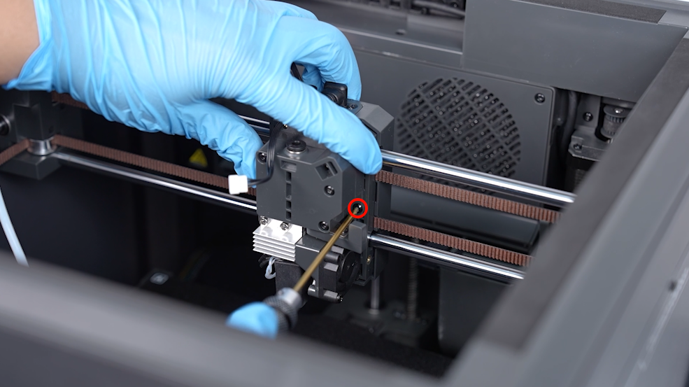
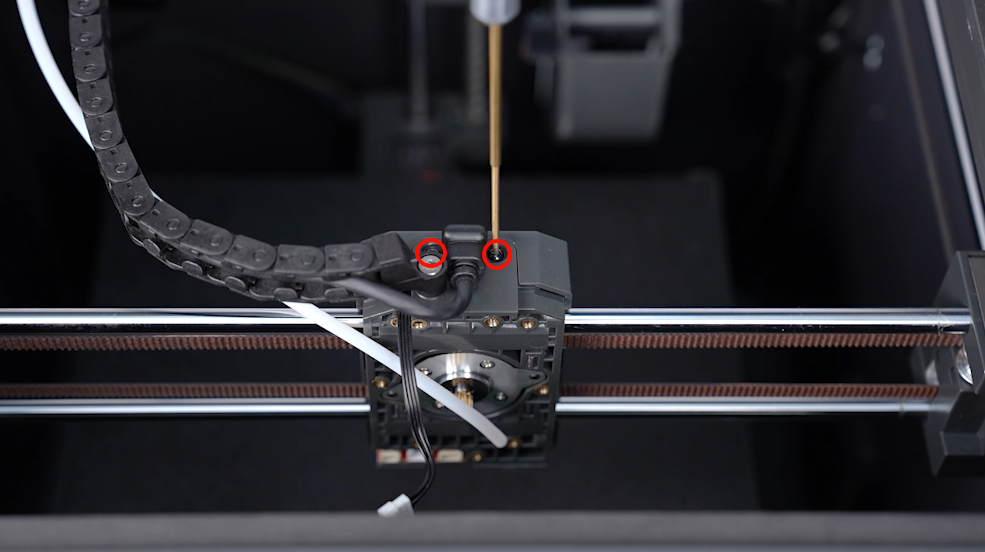
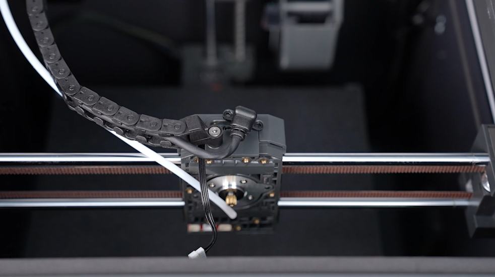
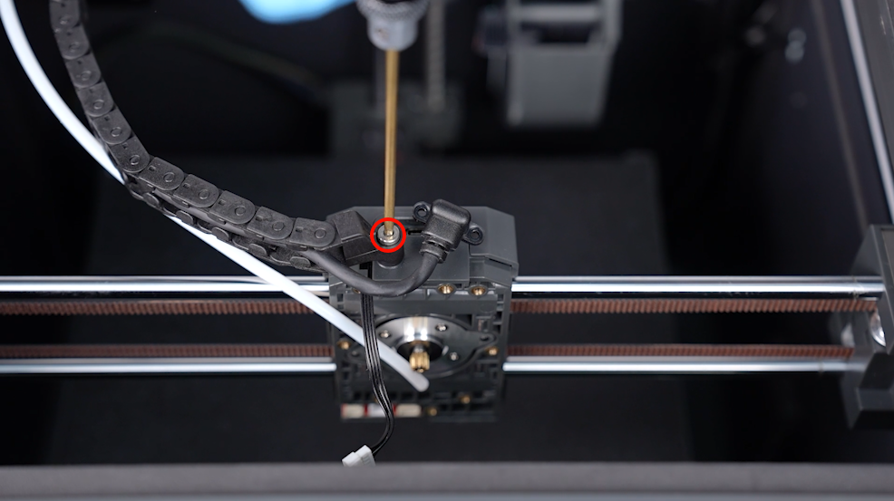
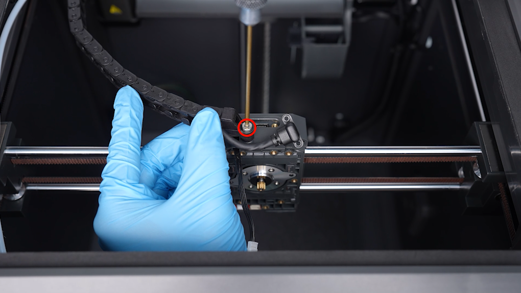
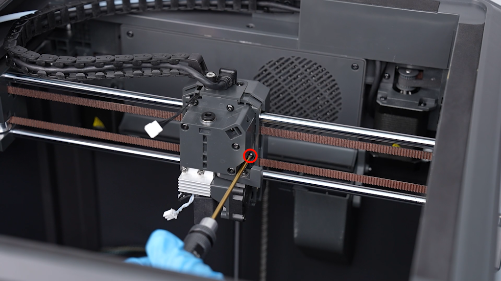
- Loosen the screw securing the heat break cooling fan assembly using a 2.0 mm Allen key. Remove the heat break cooling fan assembly.
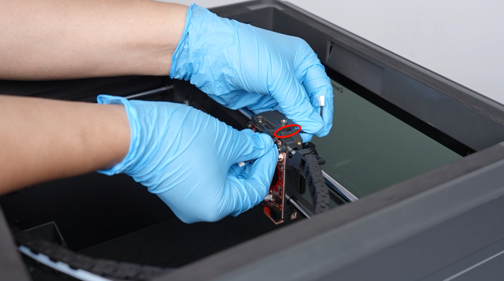
- Use a 1.5 mm Allen wrench to loosen the 2 screws securing the cable port of the print head.
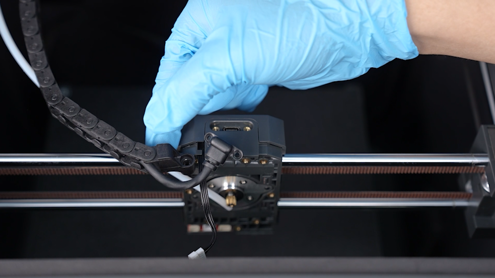
- Loosen the screw securing the cable chain front end using a 2.5 mm Allen key. Remove the cable chain front end.
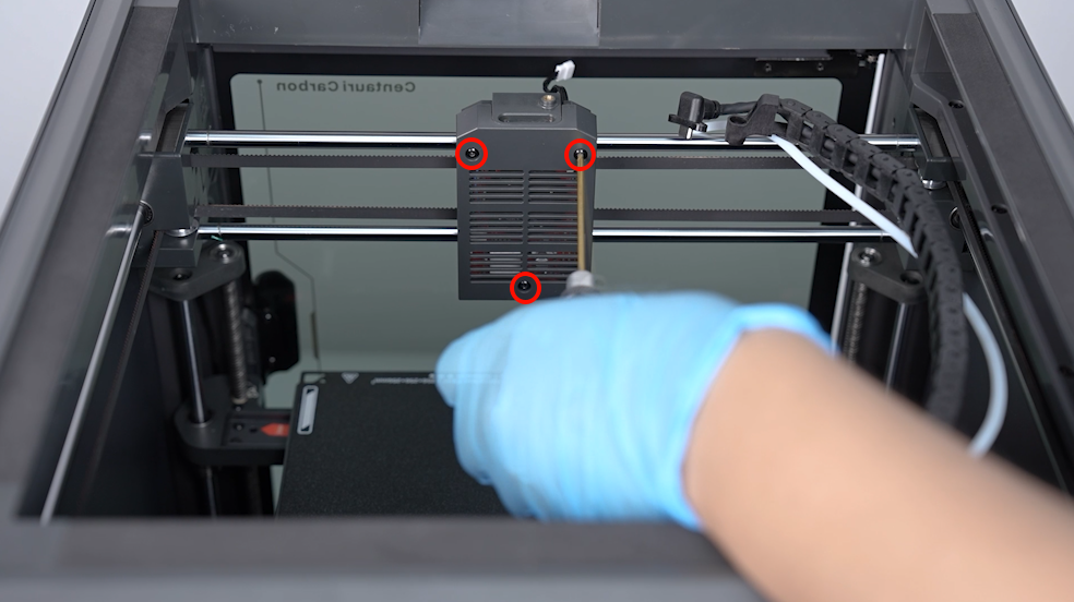
- Use a 2.0 mm Allen wrench to loosen the 3 screws securing the back cover of the printer, then remove the print head's back cover.
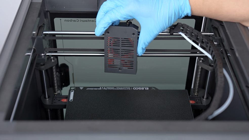
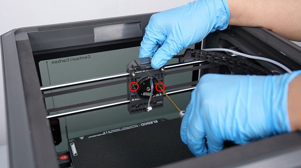
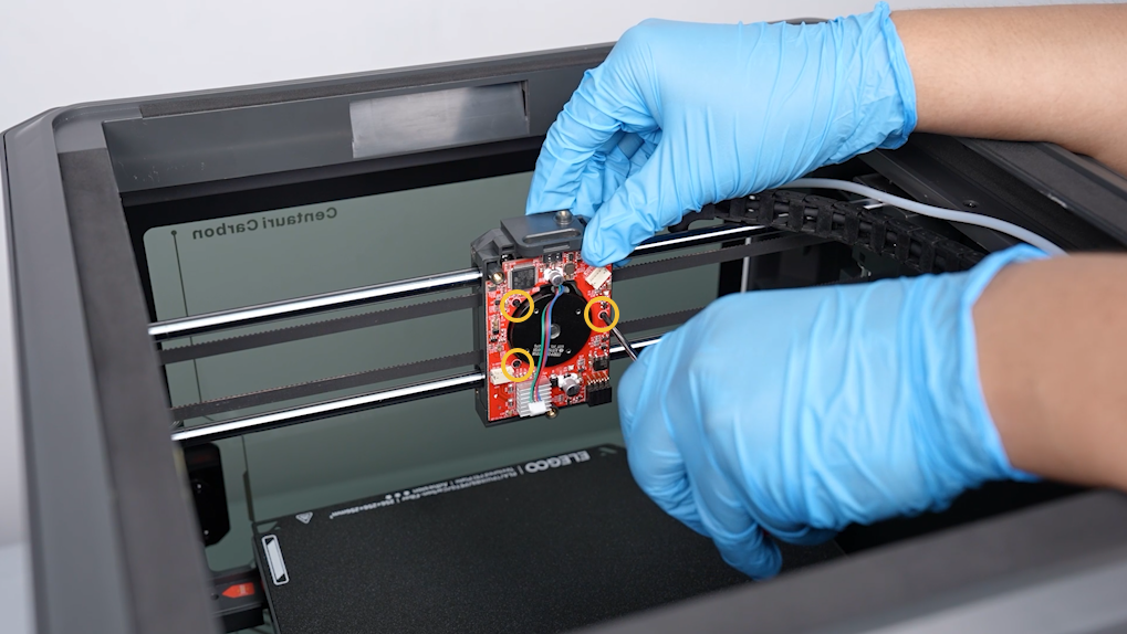
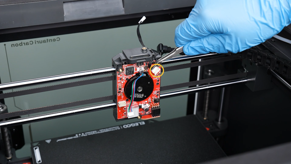
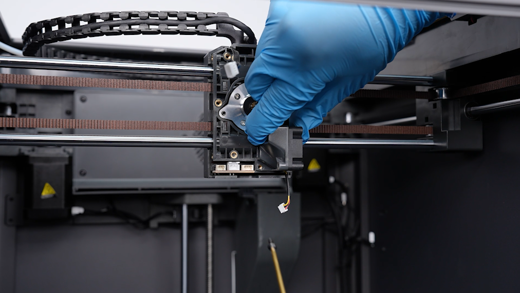
- Unplug the ribbon cables of the model cooling fan and port of the extruder motor on the PCB of the print head. Loosen the 3 screws securing the PCB of the print head.
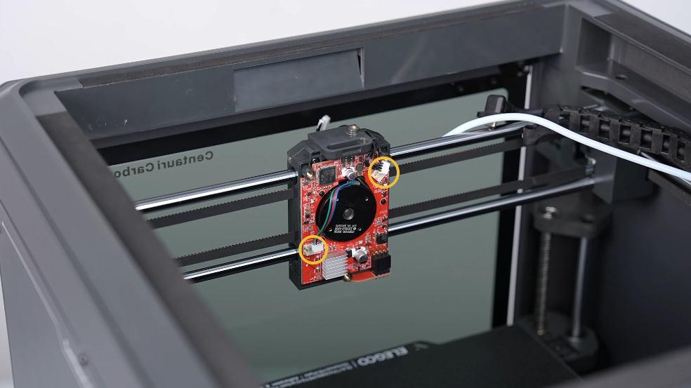
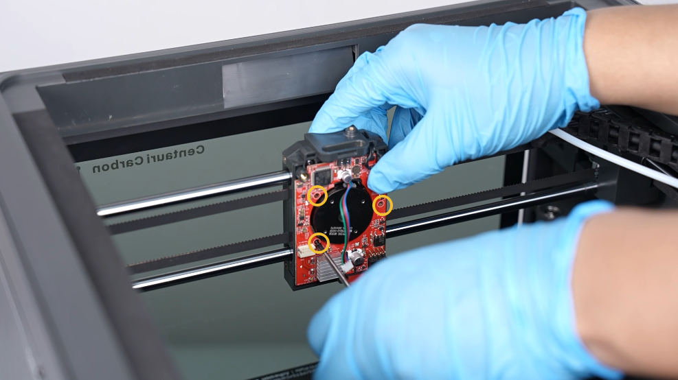
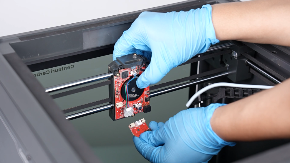
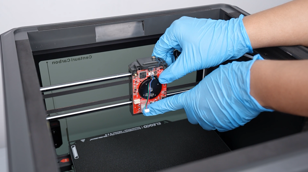
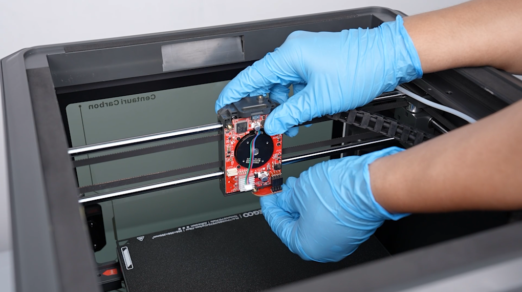
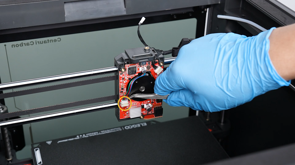
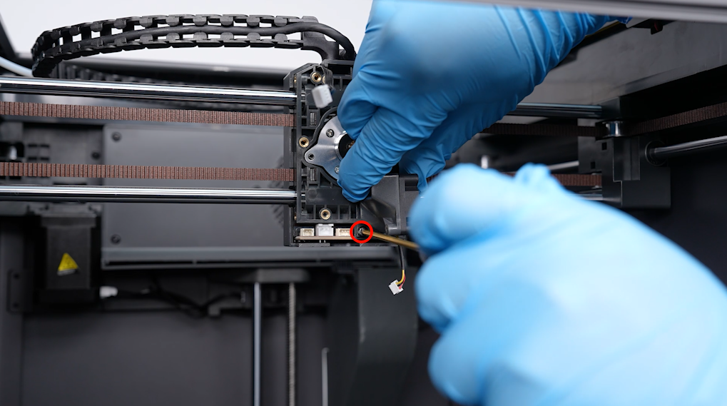
- Loosen the screw below the PCB using a 2.0 mm Allen key. Press the adpater board slightly to seperate the board and remove the old PCB of the print head.
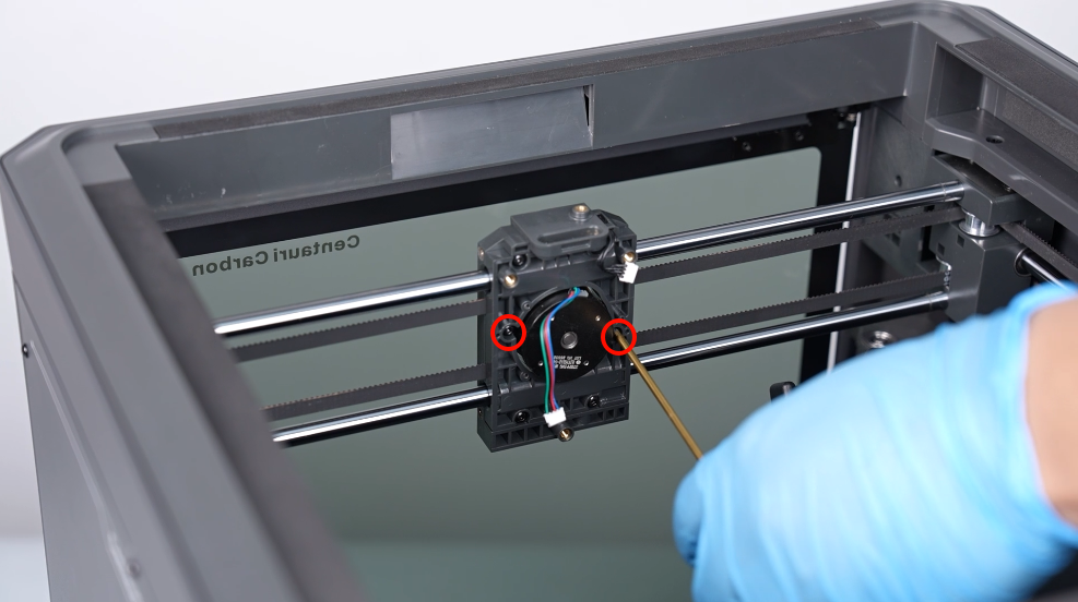
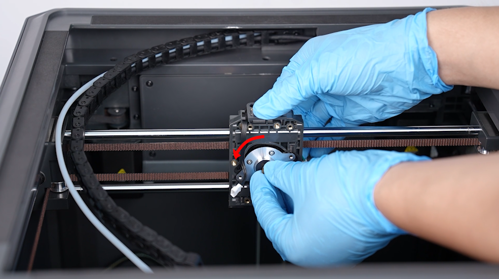
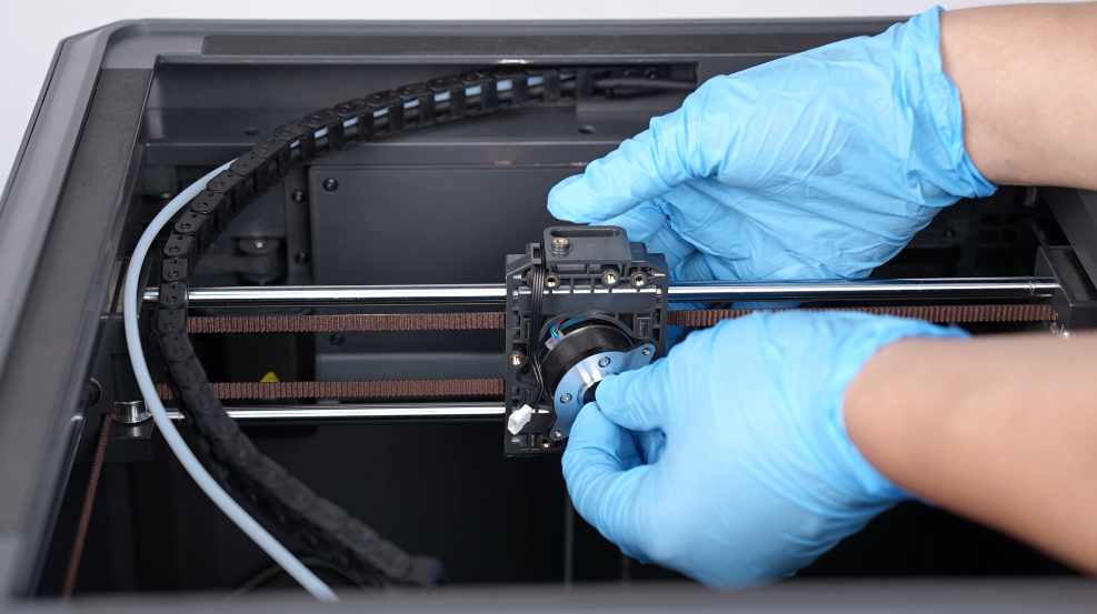
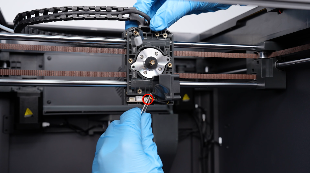
- Loosen the 2 screws securing the motor of the extruder using a 2.0 mm Allen key. Rotate the motor and remove it.
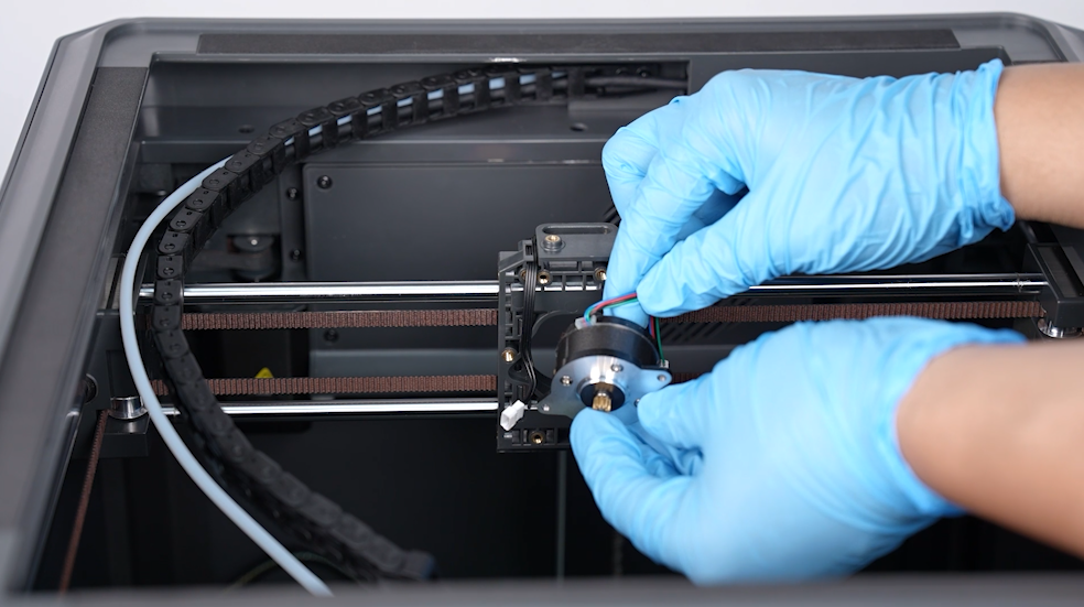
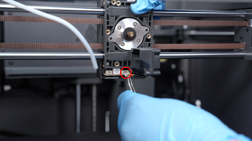
- Remove the nozzle cooling fan adapter cable.
¶ Remove the top frame
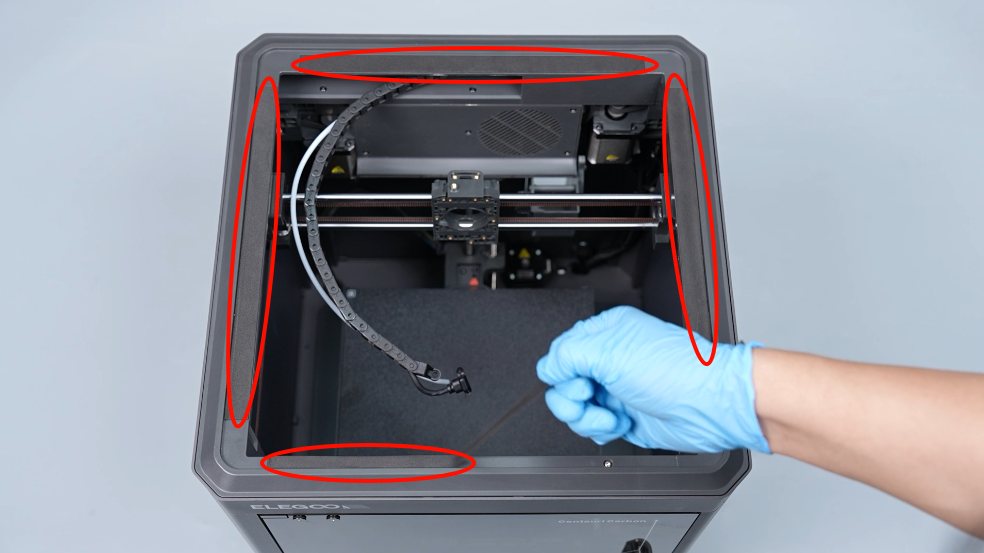
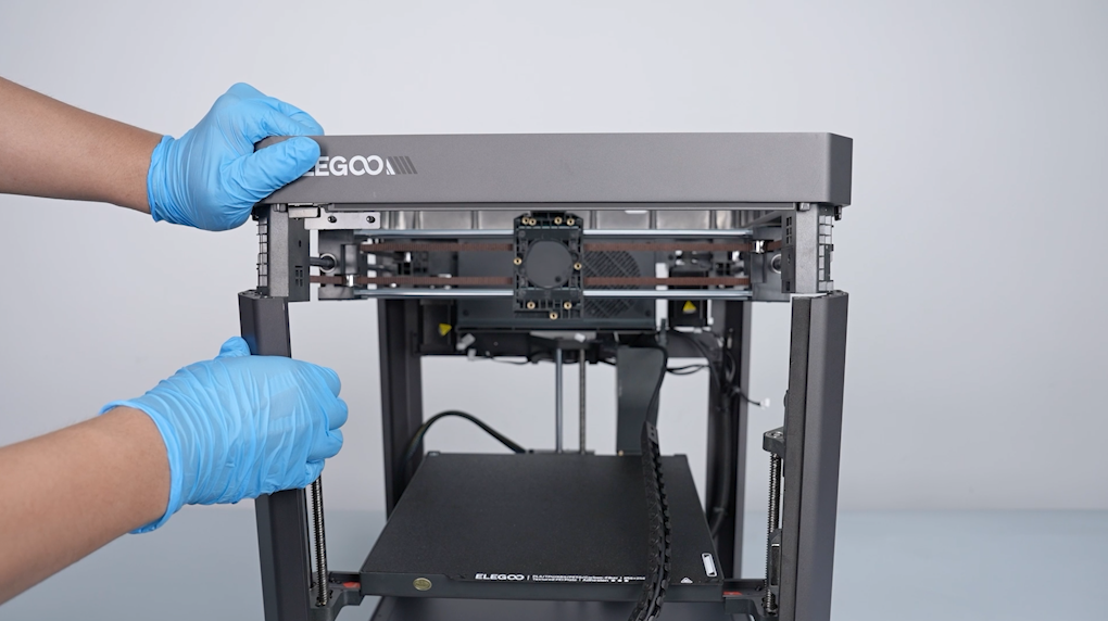
- Tear off the four pieces of shock-absorbing foam adhered to the top frame of the enclosure.
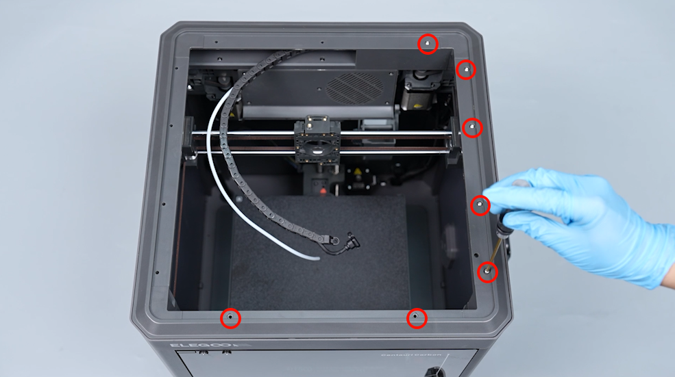
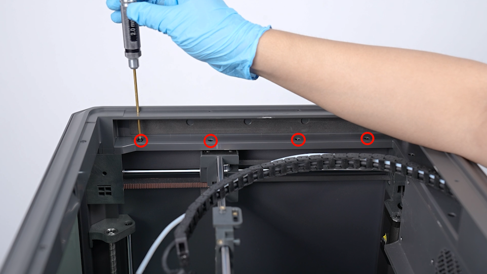
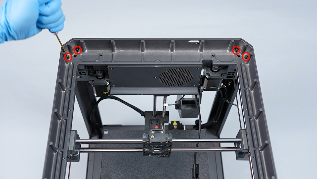
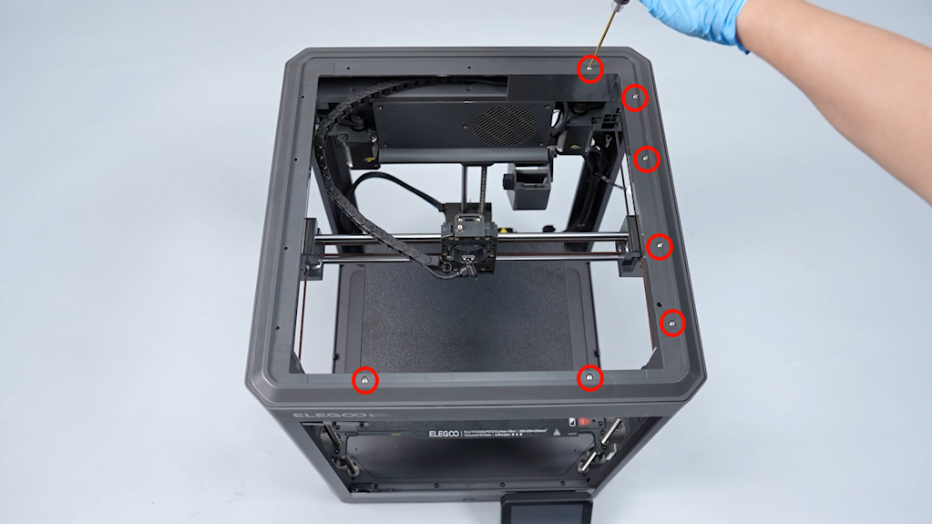
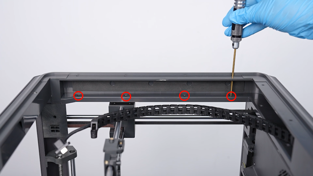
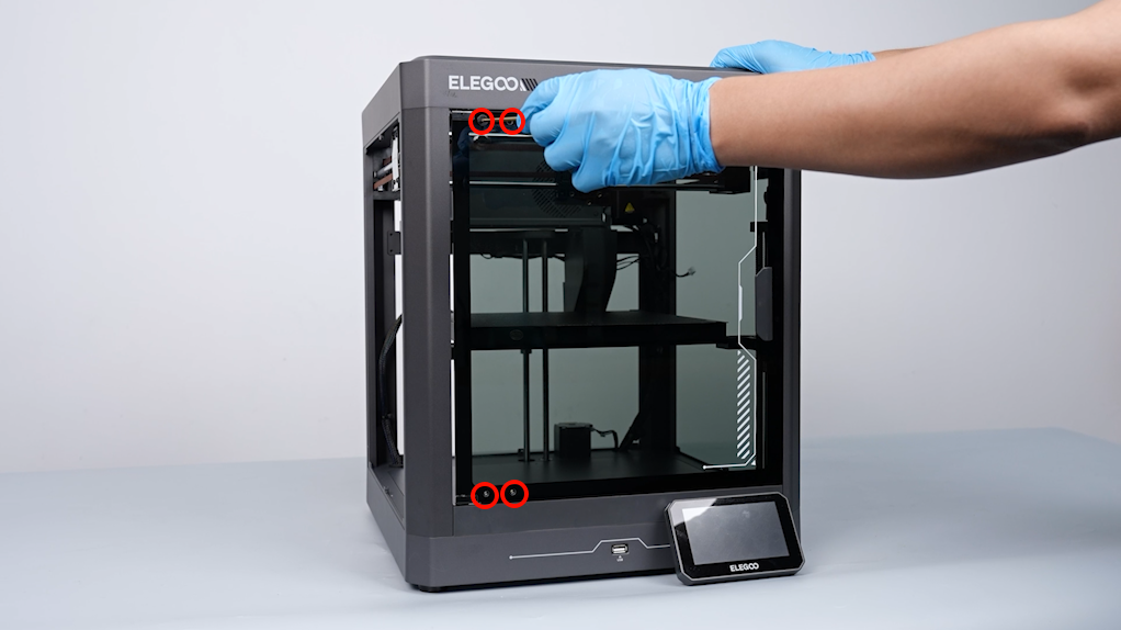
- Loosen the 7 screws securing the top frame of the plastic enclosure using a 2.0 mm Allen key.
Note: Secured in front are two short screws.
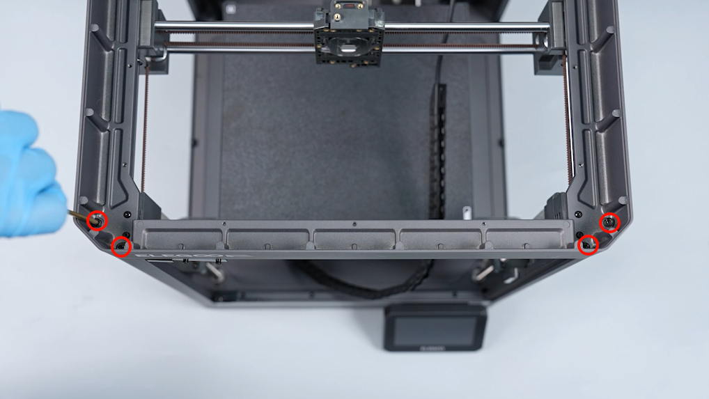
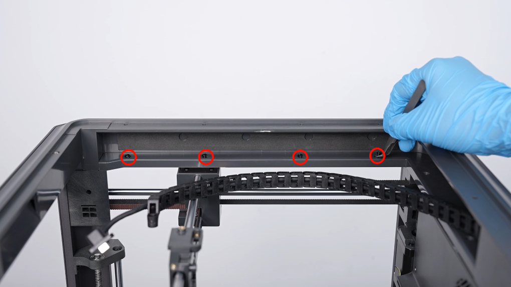
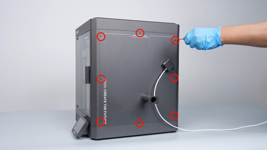
- Loosen the 6 screws securing the inner side enclosre using a 2.0 mm Allen key.
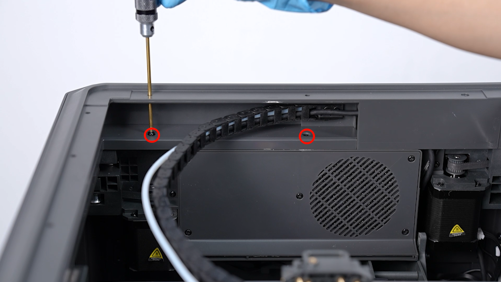
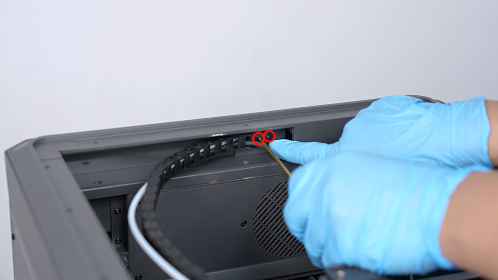
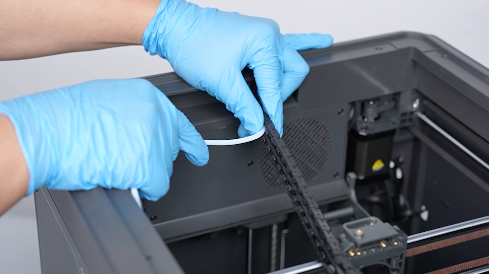
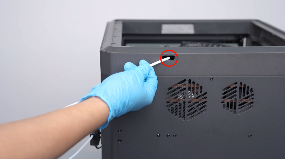
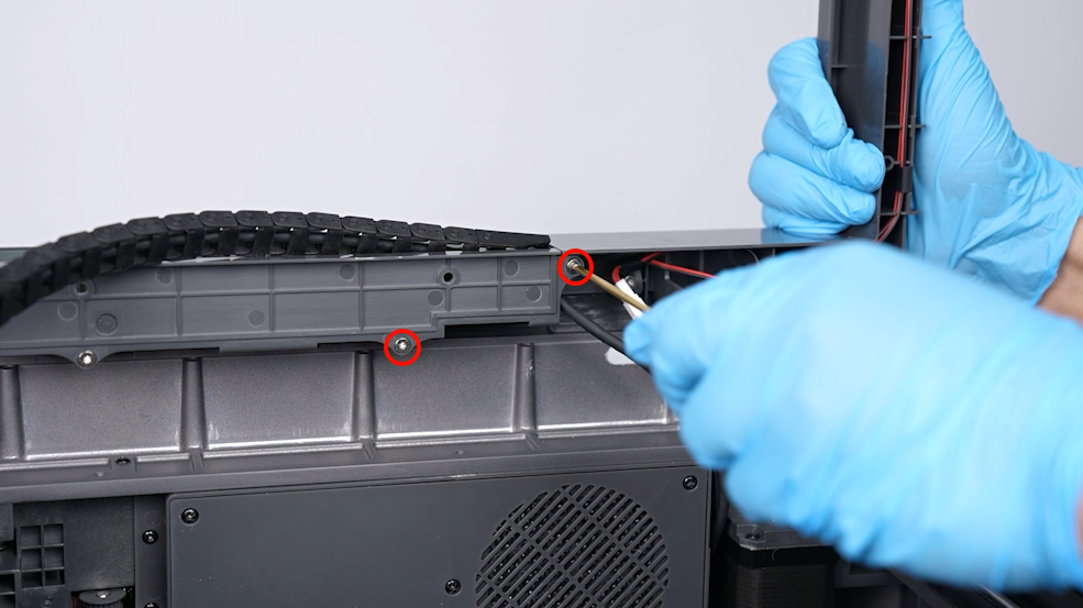
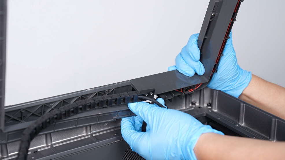
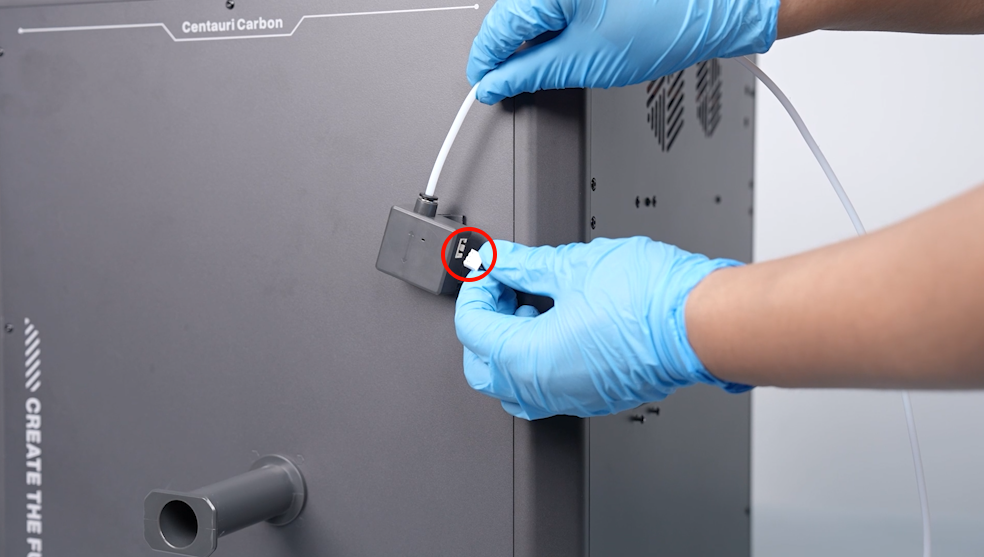
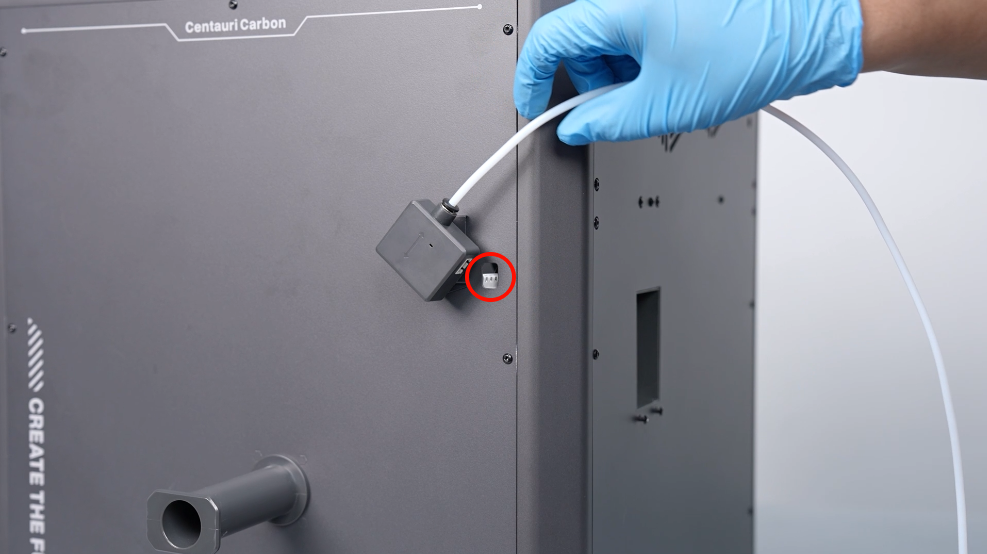
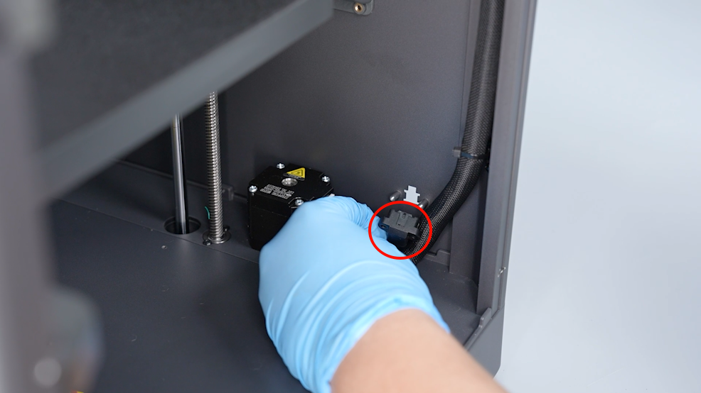
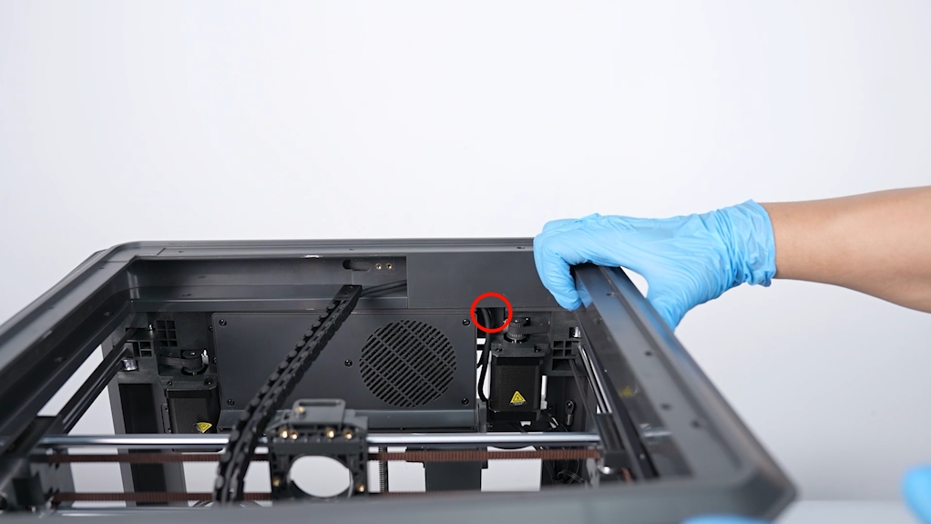
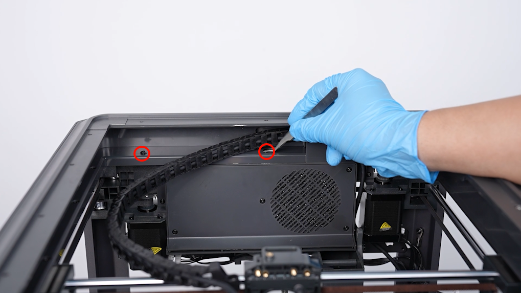
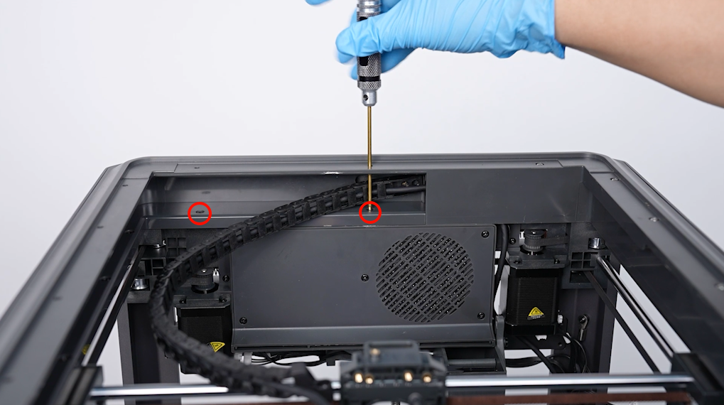
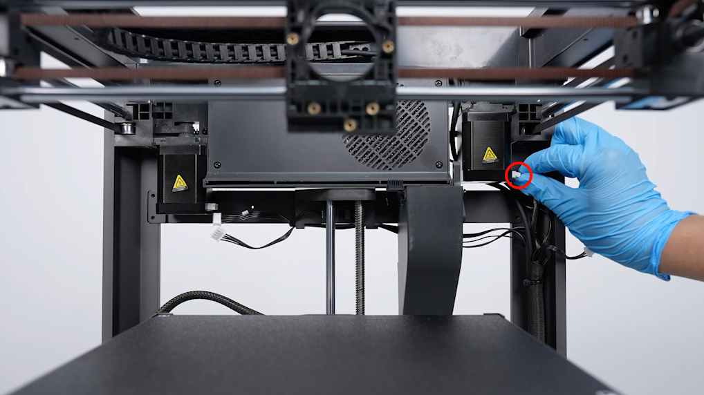
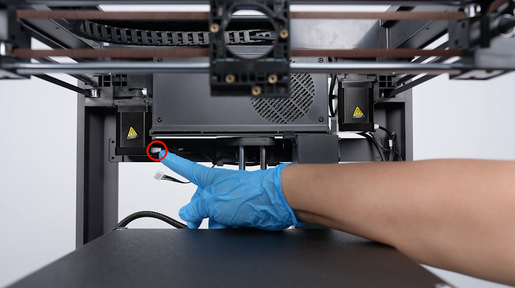
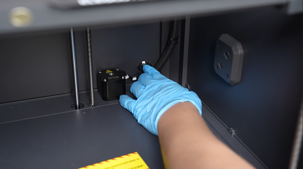
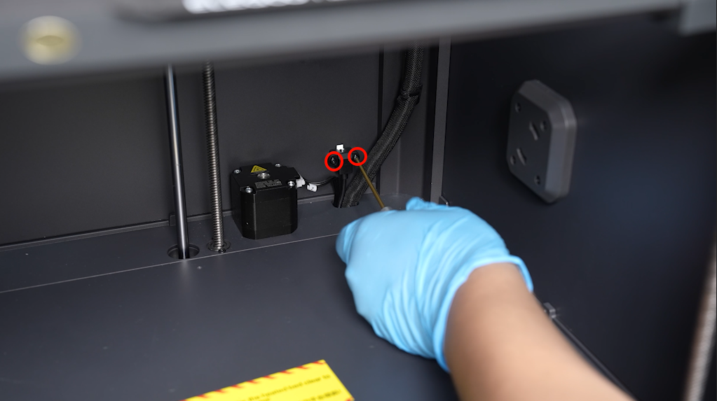
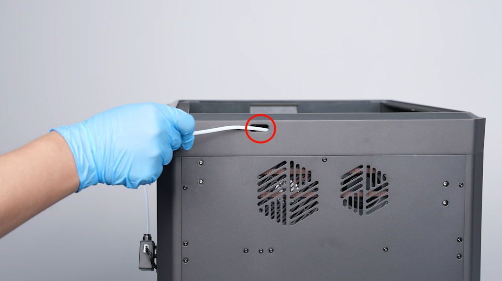
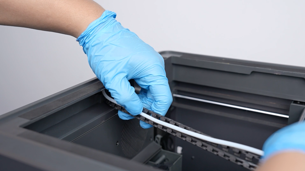
- Loosen the 2 screws securing the cable chain terminal using a 2.0 mm Allen key. Pull out the PTFE tube from the cable chain from the back side of the printer.
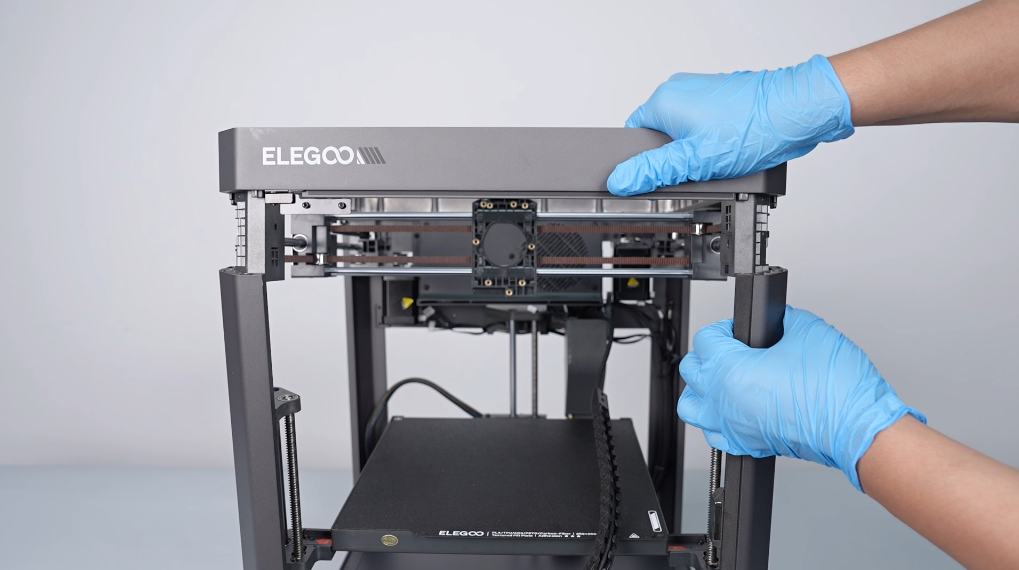
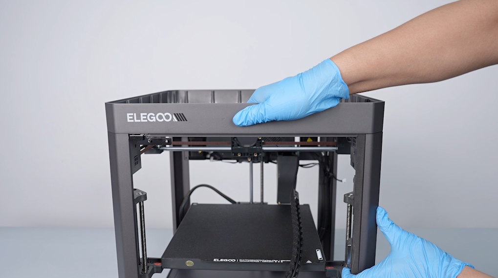
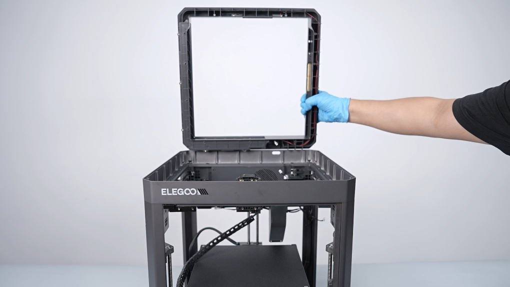
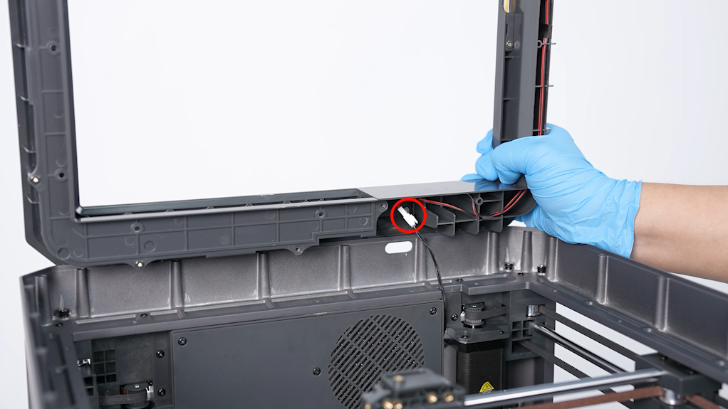
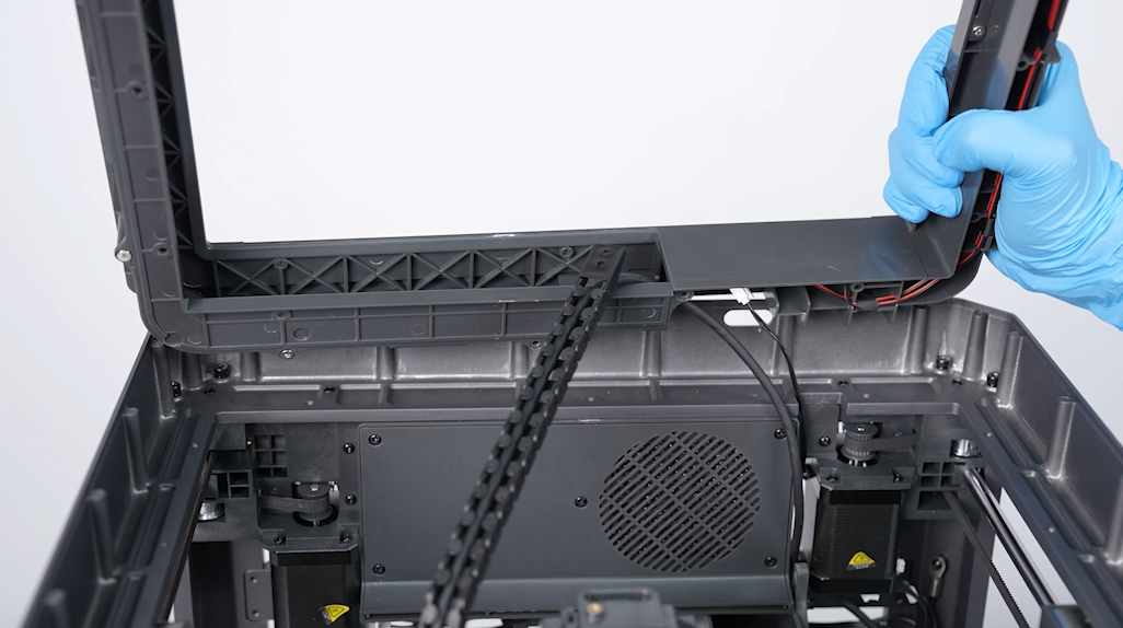
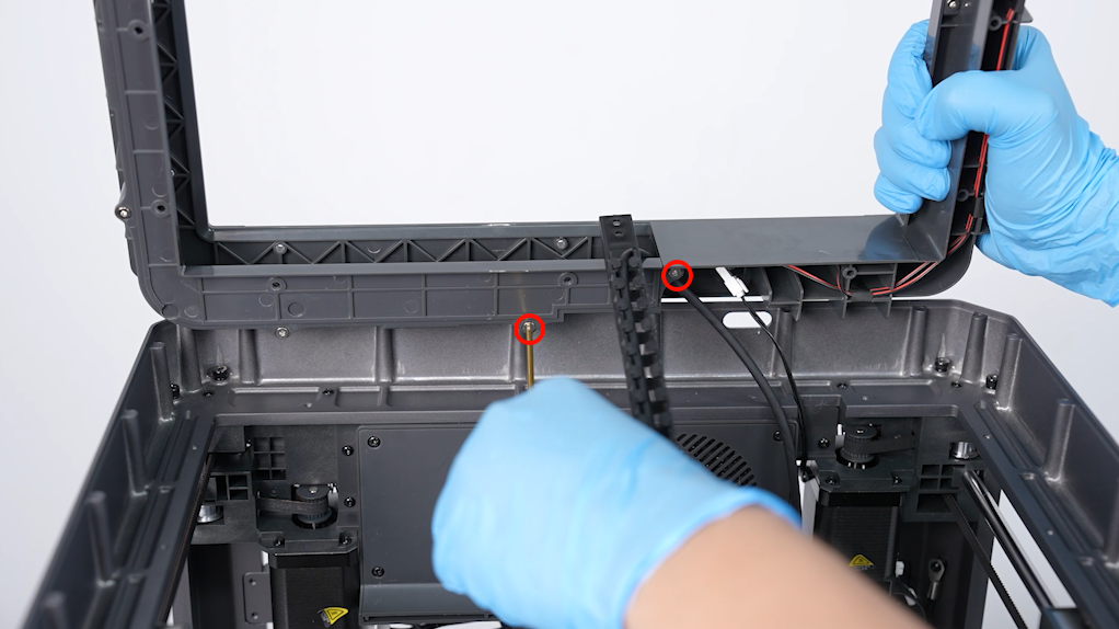
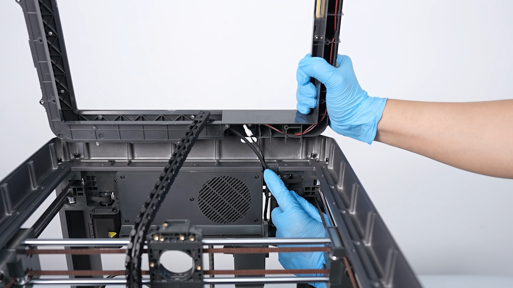
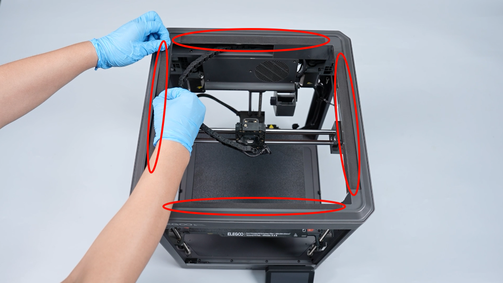
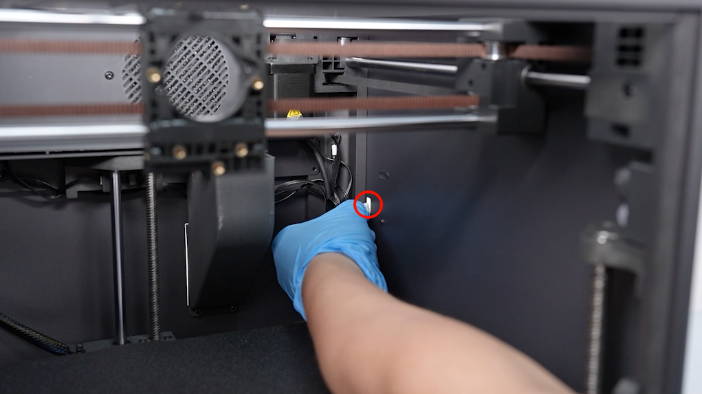
- Lift the plastic enclosure. Stand it upright on its back frame. Loosen the 2 screws securing the lower part of the plastic enclosure. Remove the print head connection cable from the top frame.
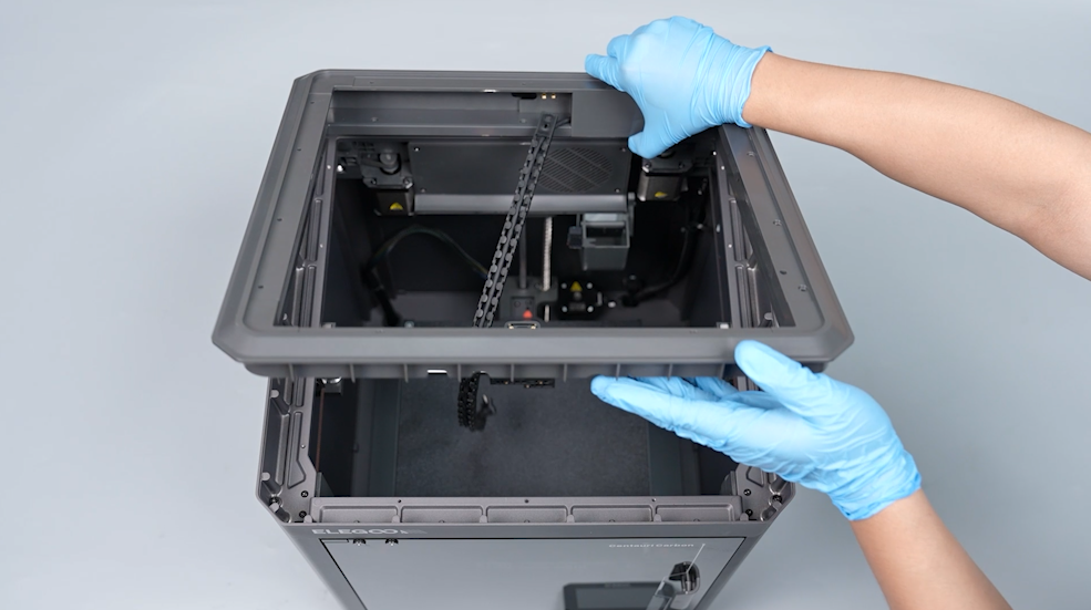
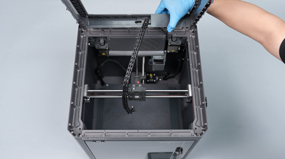
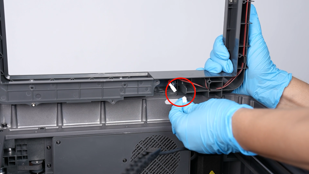
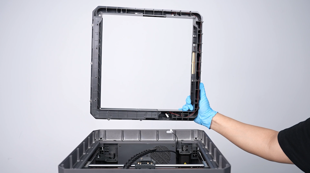
- Unplug the ribbon cable port of the strip light. Remove the plastic enclosure of the top frame.
¶ Remove the front, back, ;eft and right covers and the top metal frame
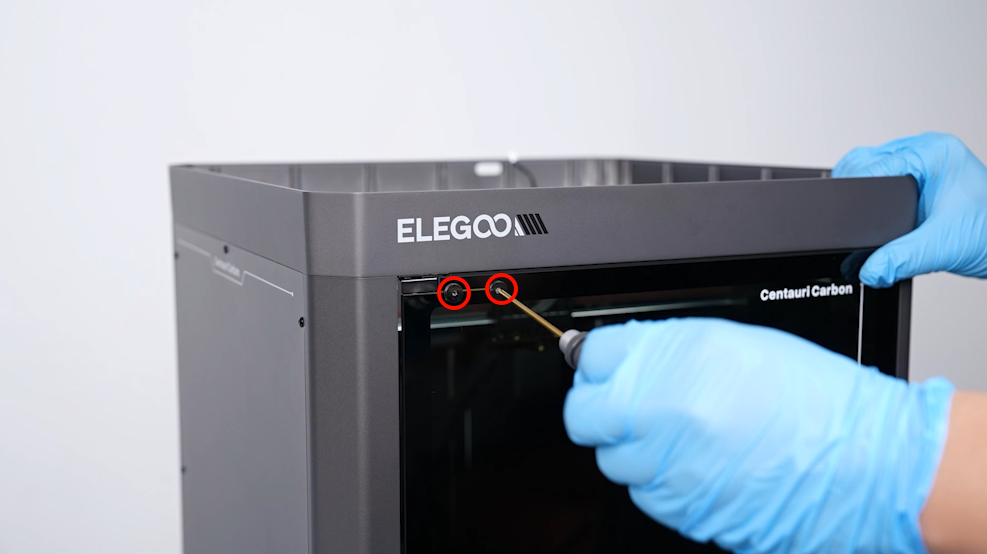
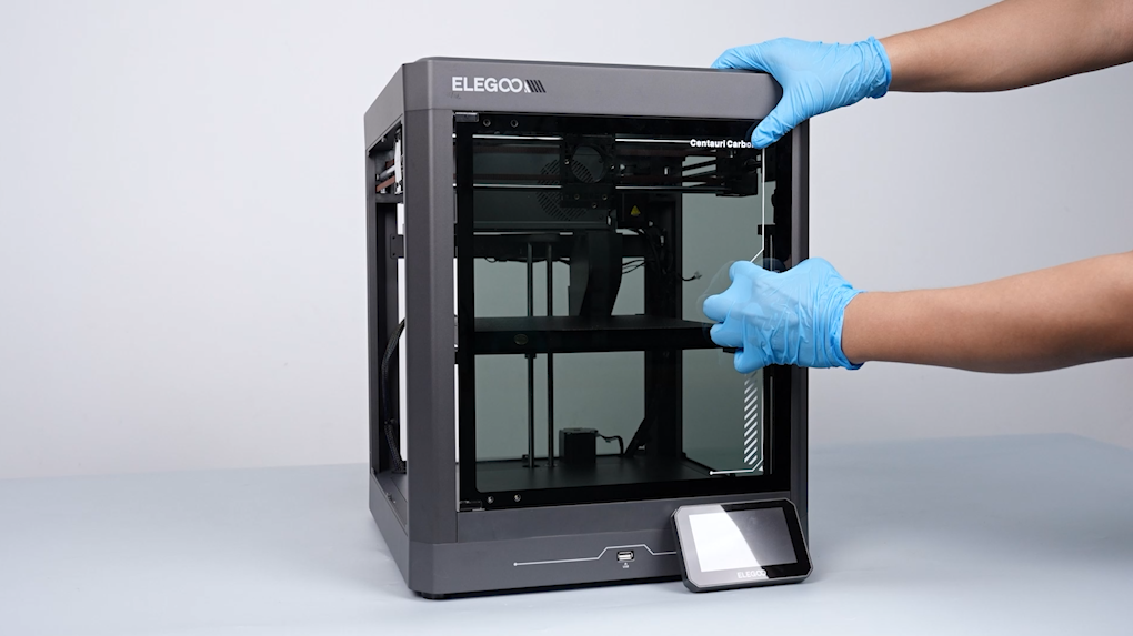
- Loosen the 4 screws securing the front glass door using a 2.0 mm Allen key. Remove the front door.

- Unplug the ribbon cables of the filament runout detection port. Pass the ribbon cables inside the printer through the ribbon cable hole.
- Loosen the 8 screws holding the right-side cover using a 2.0 mm Allen key. Remove the cover.
- Loosen the 2 screws securing the multi-color connector using a 2.0 mm Allen key. Remove connector.
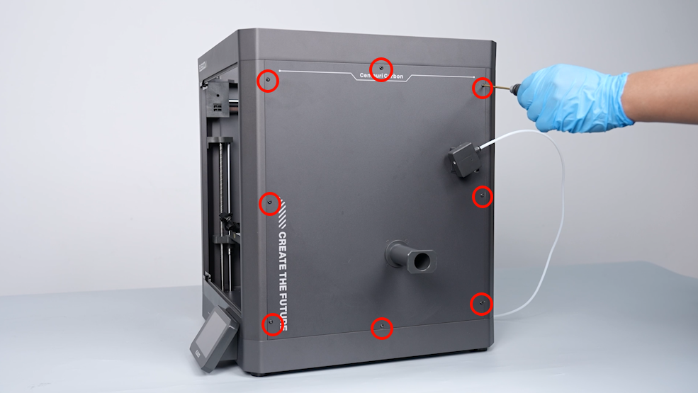
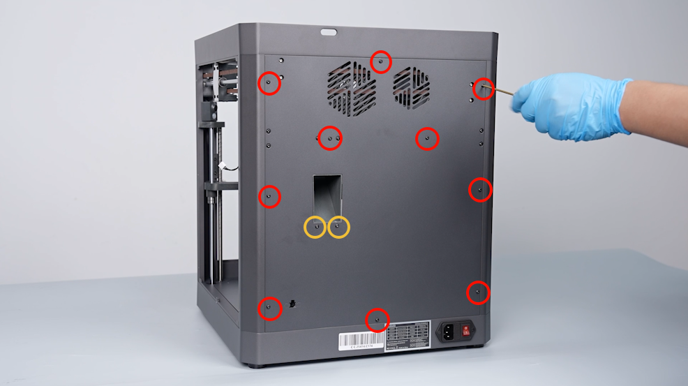
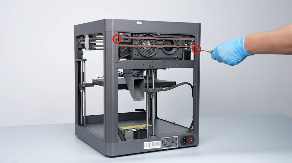
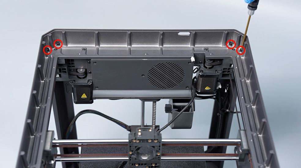
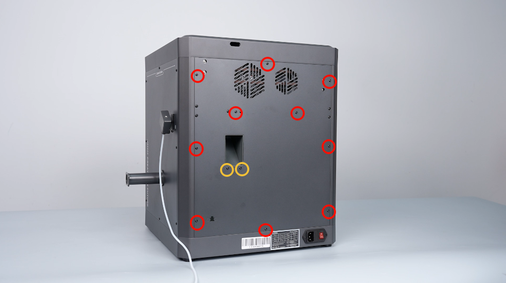
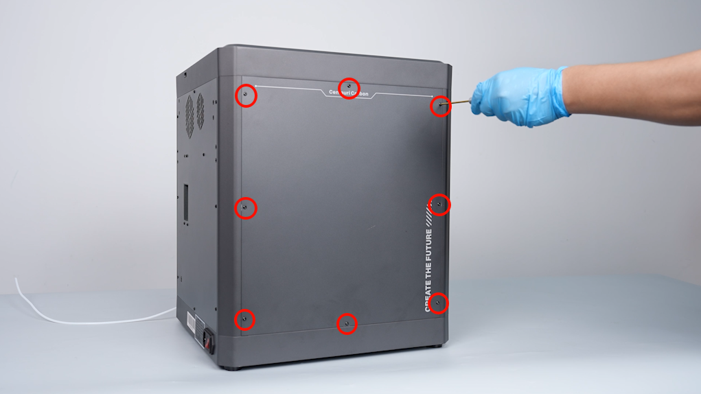
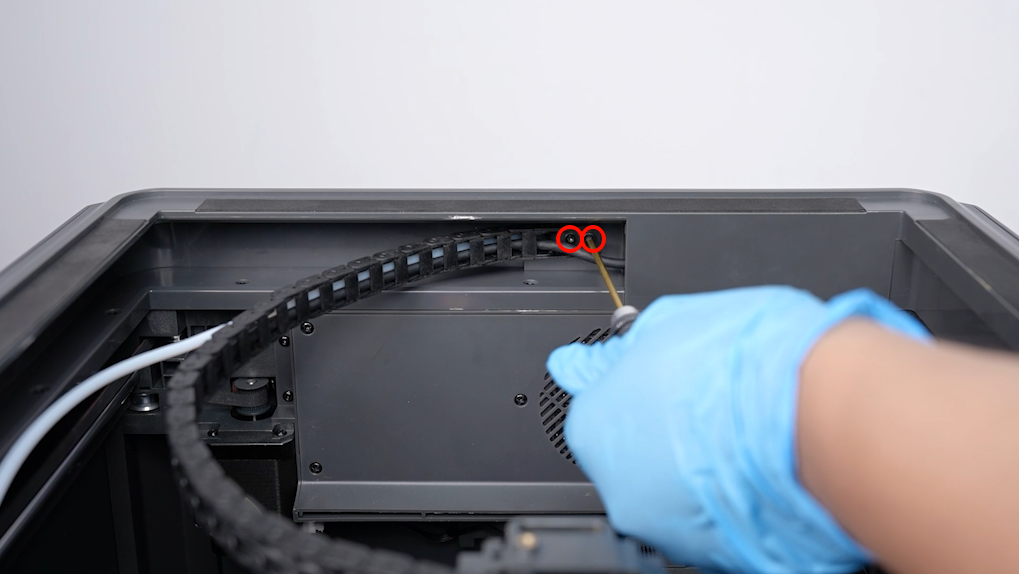
- Loosen the 12 screws securing the back cover of the printer using a 2.0 mm Allen key. Remove the back cover.
Note: Screw holes labeled by the red circle are M3*4, while screw holes labeled by the yellow circle are M3*8.
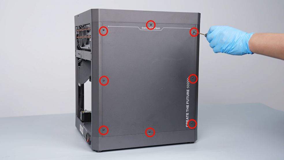
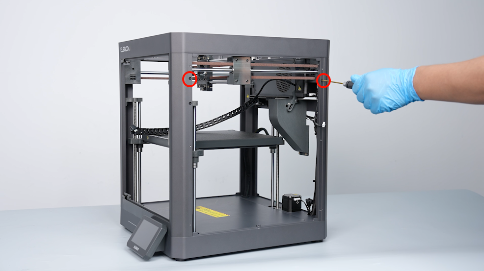
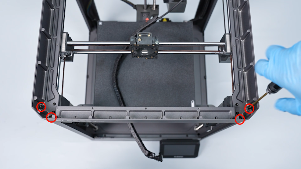
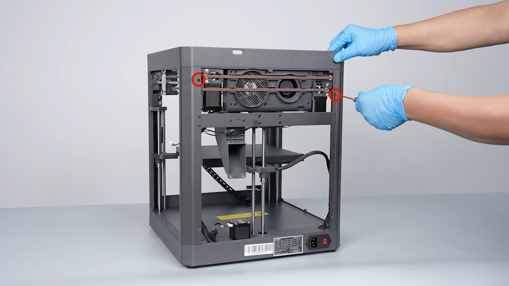
- Loosen the 8 screws holding the left-side cover using a 2.0 mm Allen key. Remove the cover. Loosen the 6 screws securing the two sides of the printer and the top metal frame of the backside pillar.
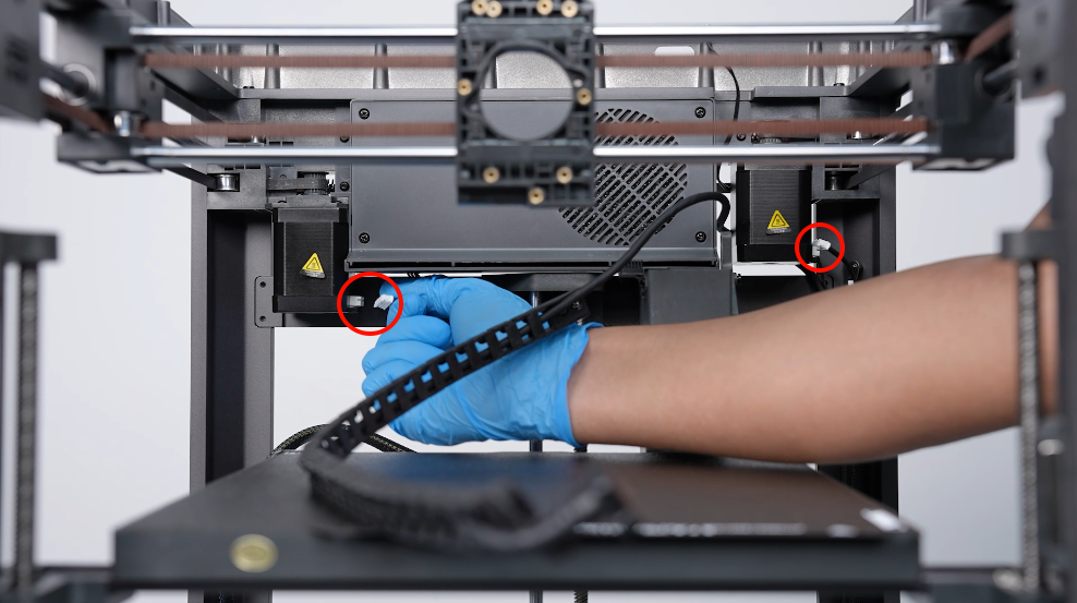
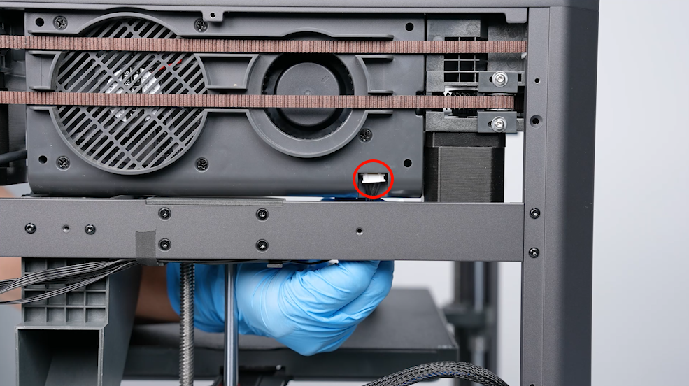
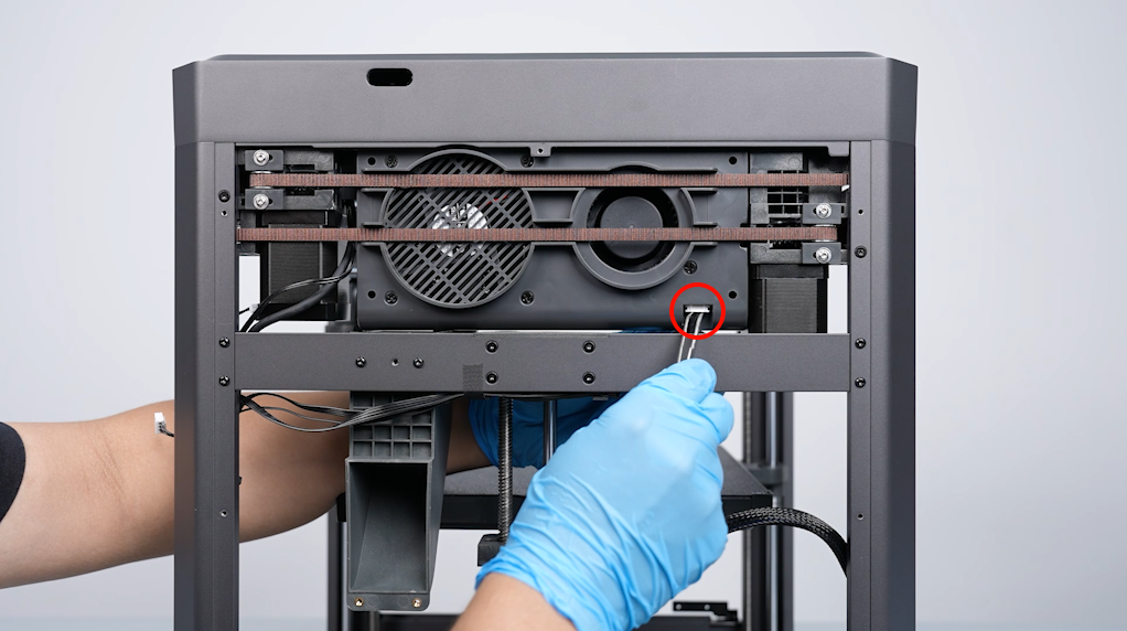
- Remove the ribbon cables of the two print head moving motors and unplug the ribbon cables of the adapter board port of auxiliary cooling fan.
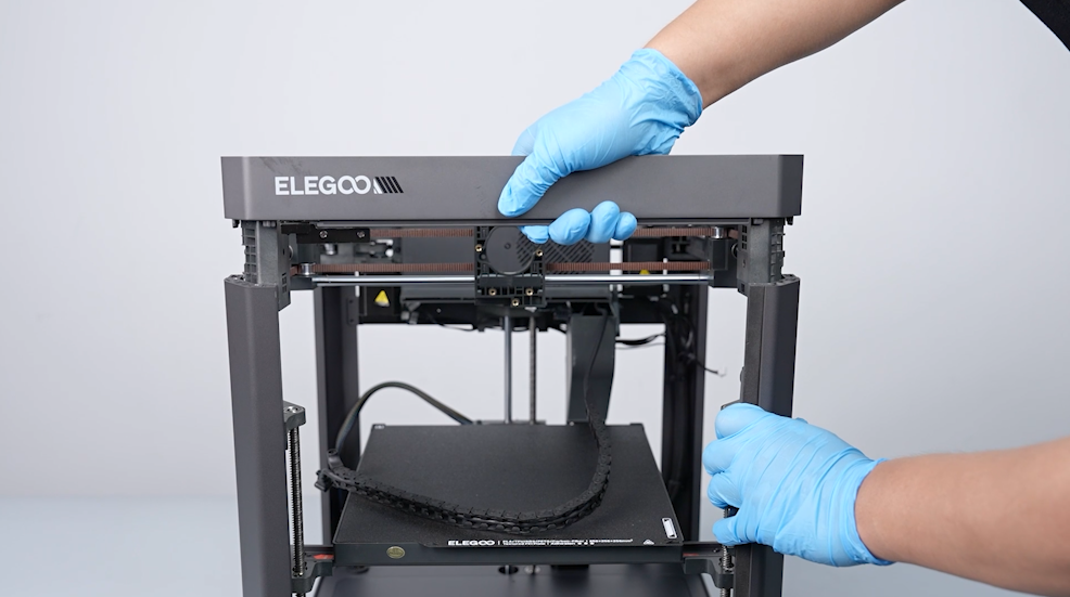
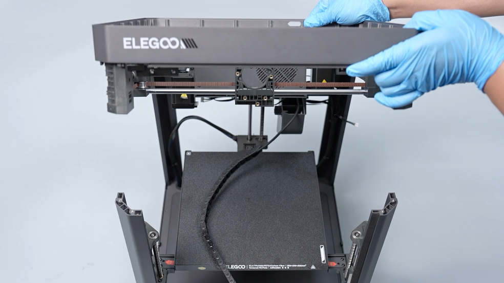
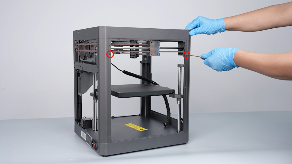
- Loosen the 8 screws securing the top metal frame using a 3.0 mm Allen key.
- Lift the front part of the top metal frame. Remove the whole top metal frame.
¶ Remove the components securing the timing belt
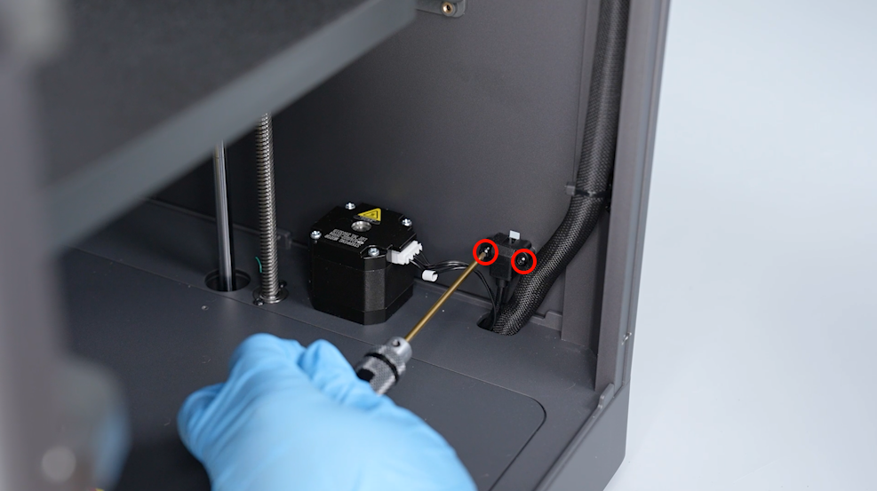
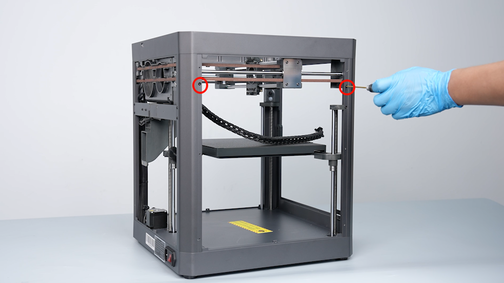
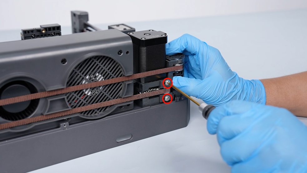
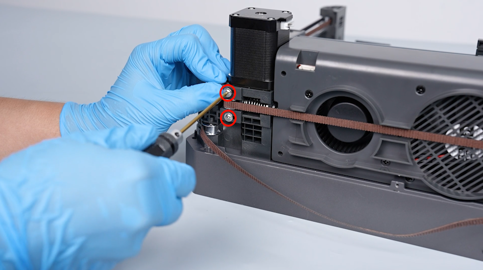
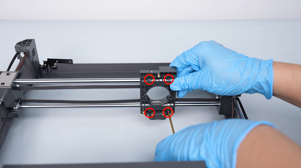
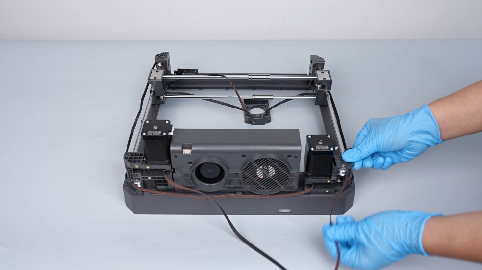
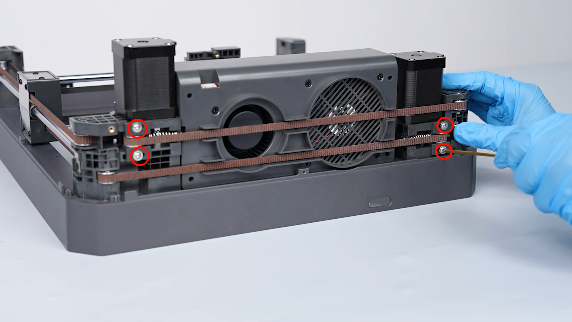
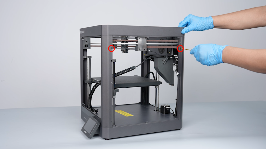
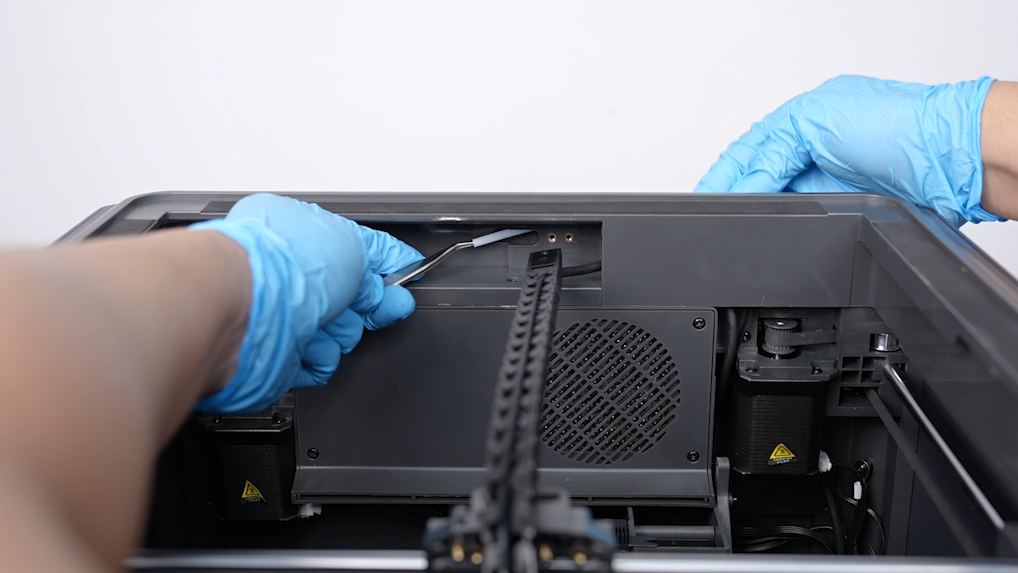
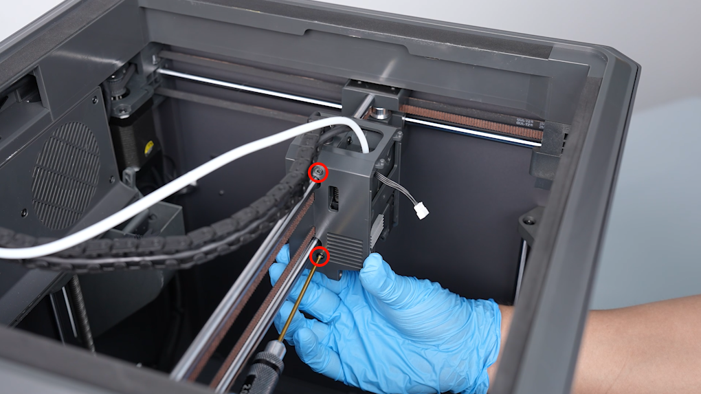
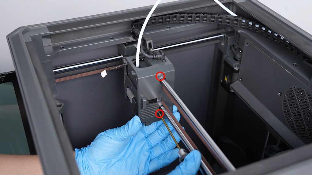
- Loosen the 2 screws securing the belt tensioner using a 2.0 mm Allen key from the back side of the print head moving assembly. Remove the belt tensioner and the spring. Loosen and remove the belt tensioner and the spring on the other side.
- Loosen the 4 screws securing metal plate for fixing at the outside of the fixing block of the X-axis plain shaft using a 2.0 mm Allen key. Remove the metal plate for fixing.
- Loosen and remove the metal plate for fixing on the other side in the same way.
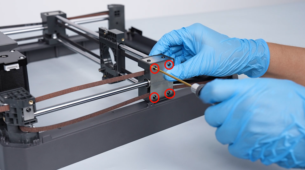
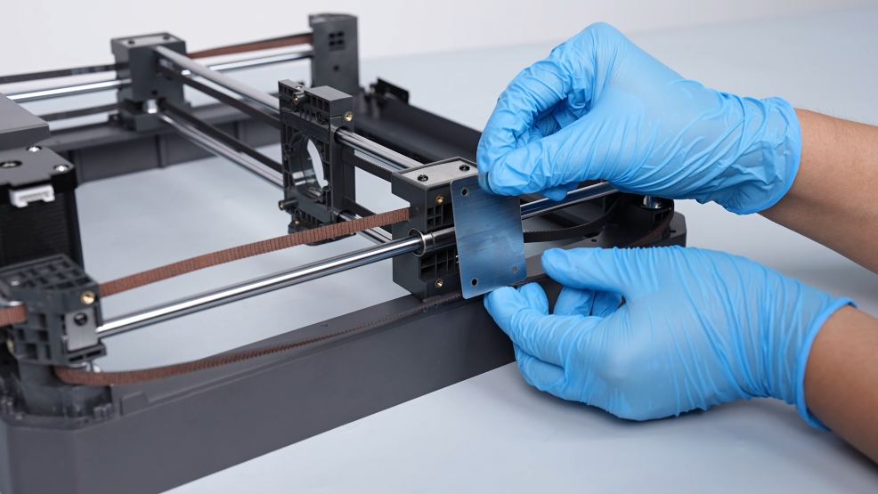
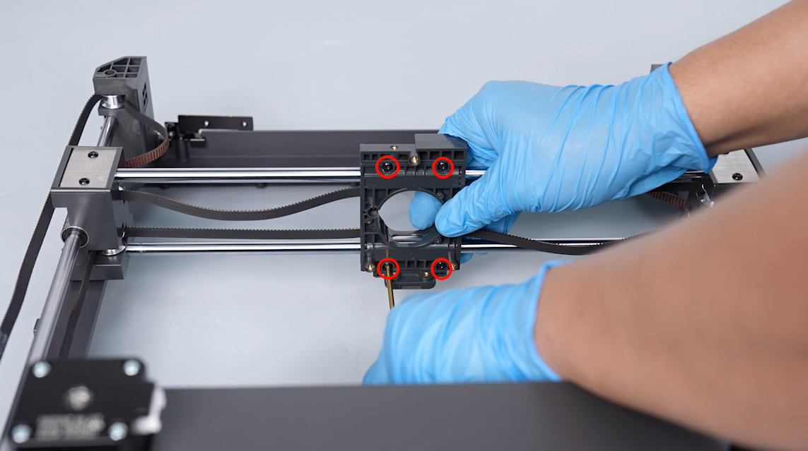
- Loosen the 4 screws securing the belt pressure plate using a 2.0 mm Allen key. Remove the belt pressure plate.
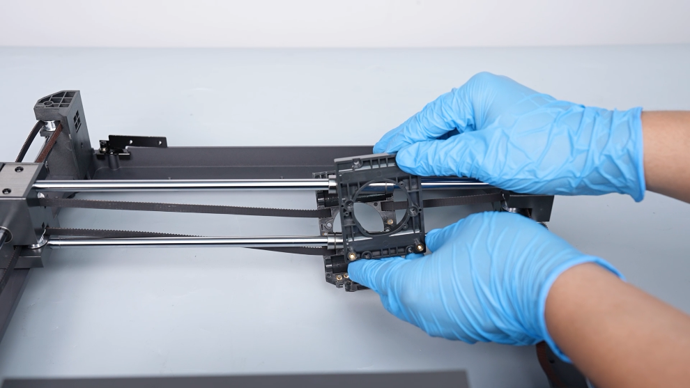
¶ Remove the old timing belt
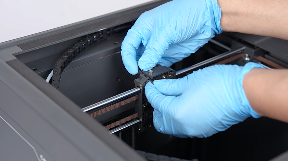
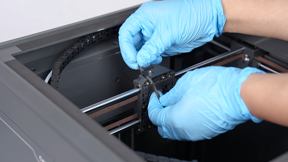
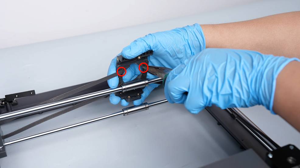
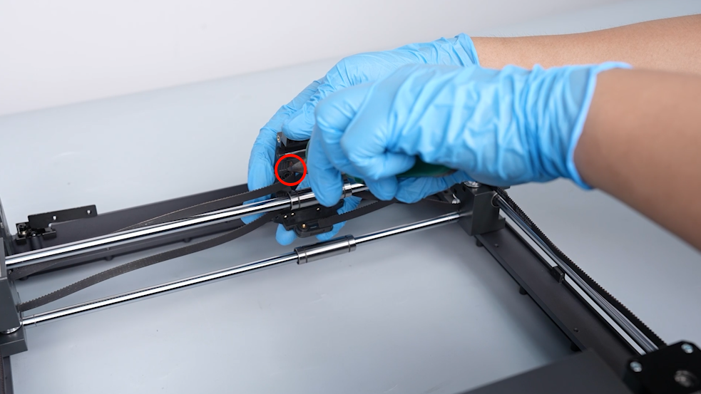
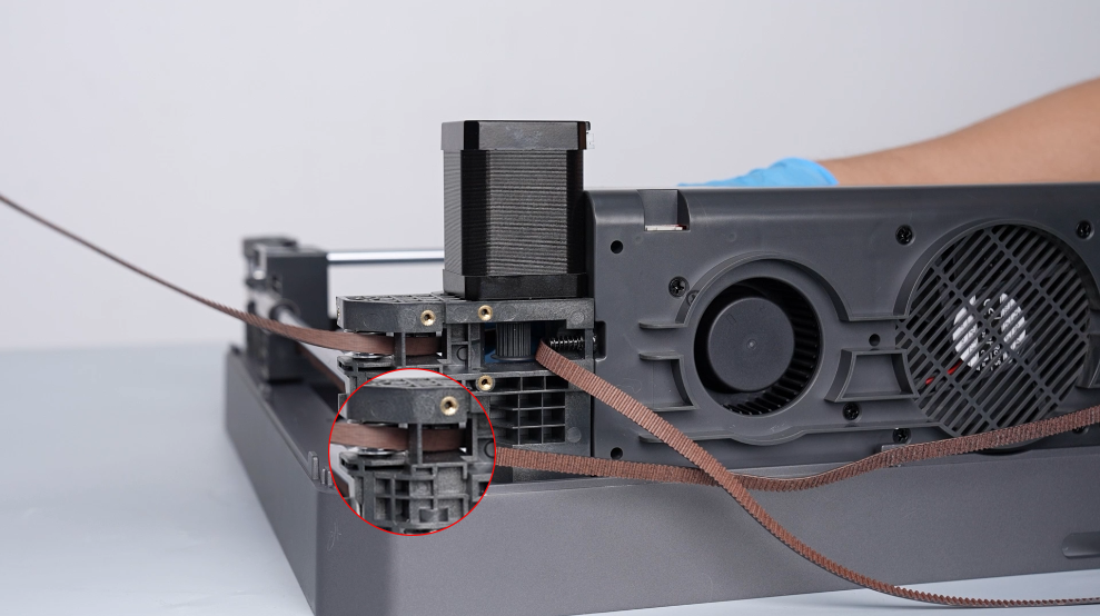
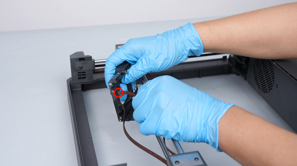
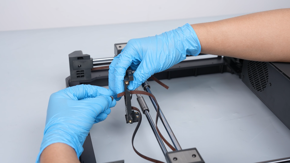
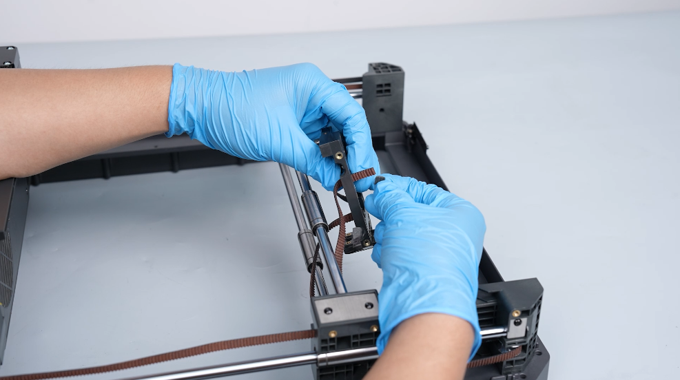
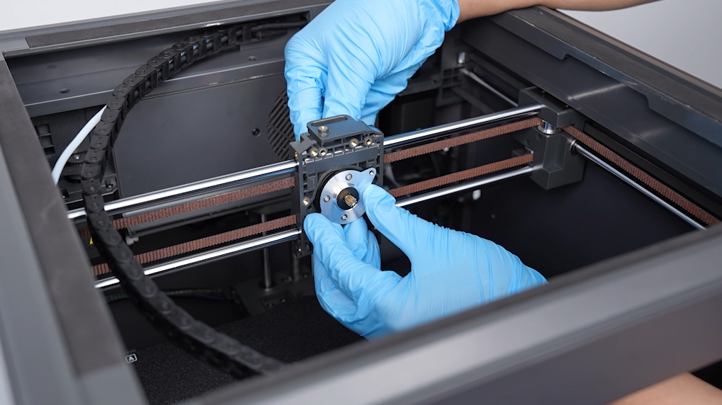
- Remove the 2 ends of the timing belt passed through the upper two ports of the fixing block using a pair of needle-nose pliers. Pull out the old timing belt from the timing pulley.
Note: Collect the two timing belt clips for installation later.
¶ Install the new timing belt
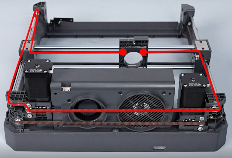
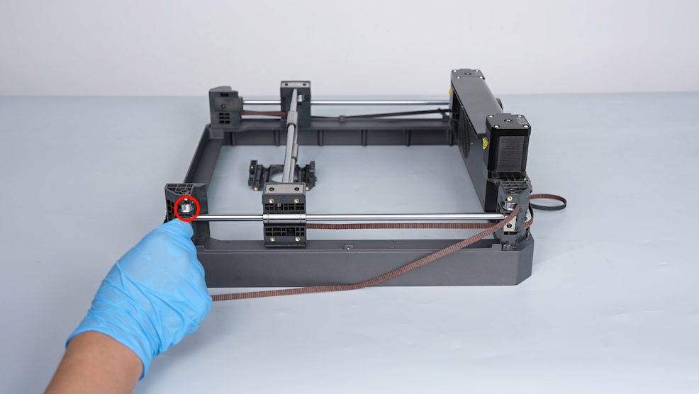
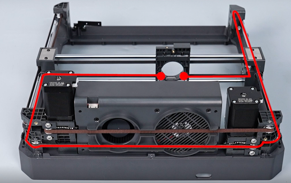
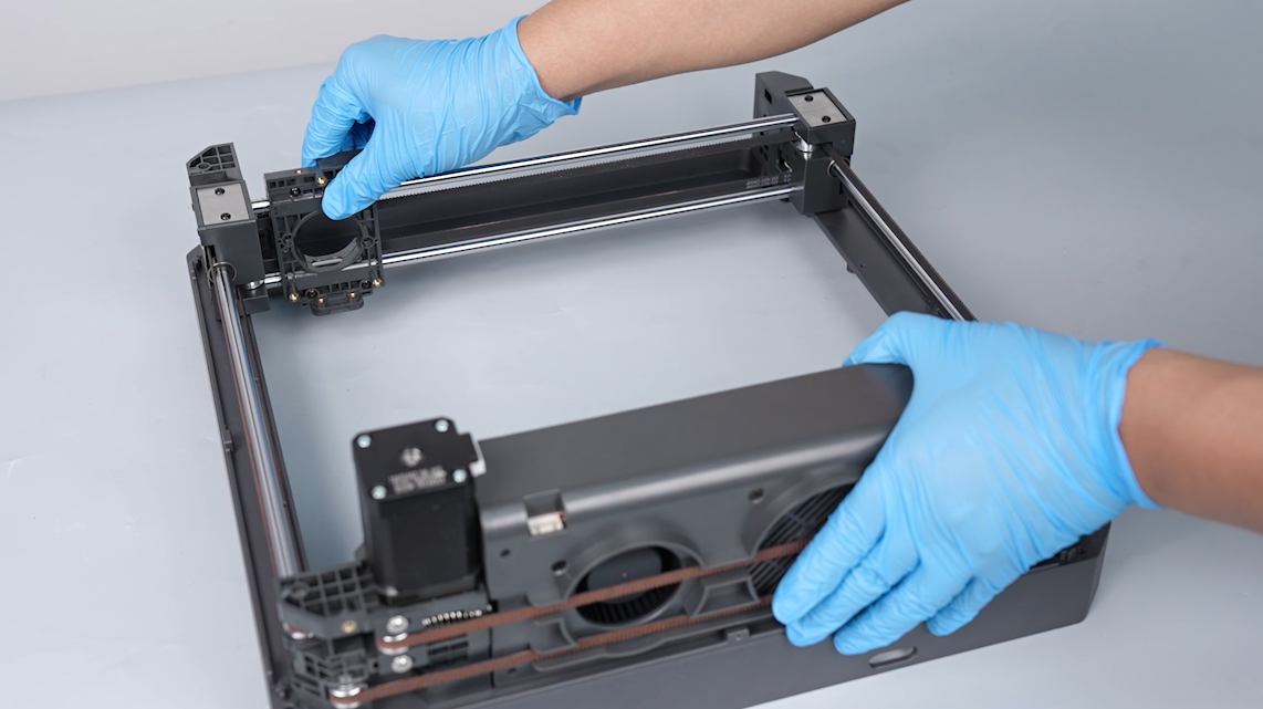
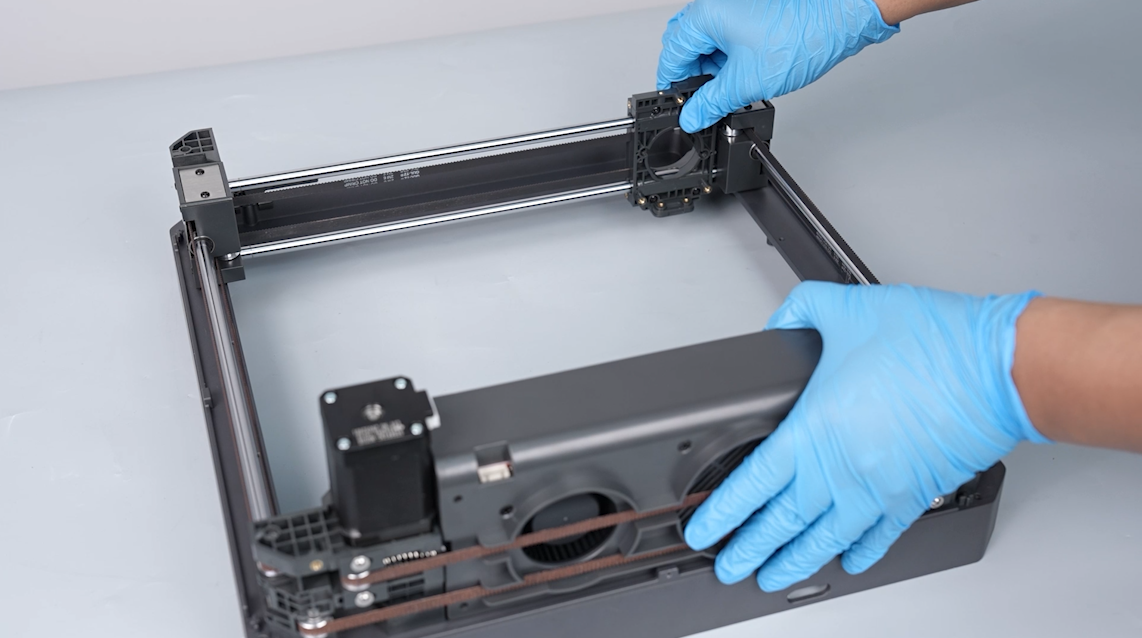
- Install the timing belt on the timing pulleys and the idler pulleys.
Note: Align the gear tooth of the timing belt with that of the timing pulleys.
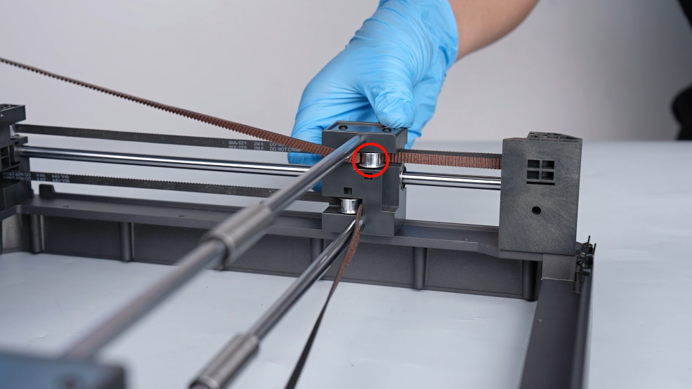

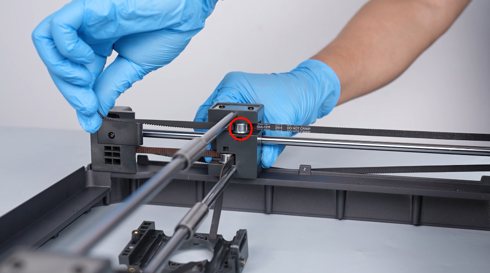
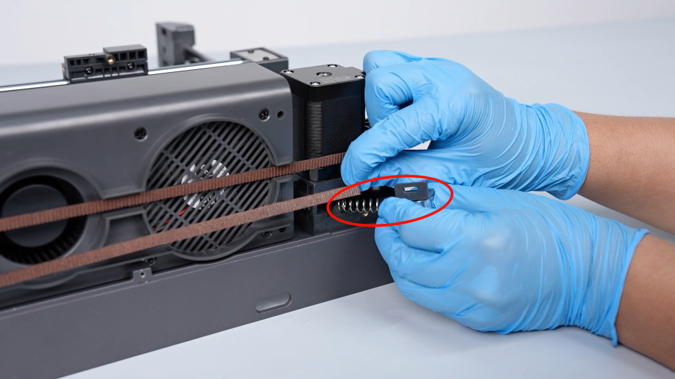
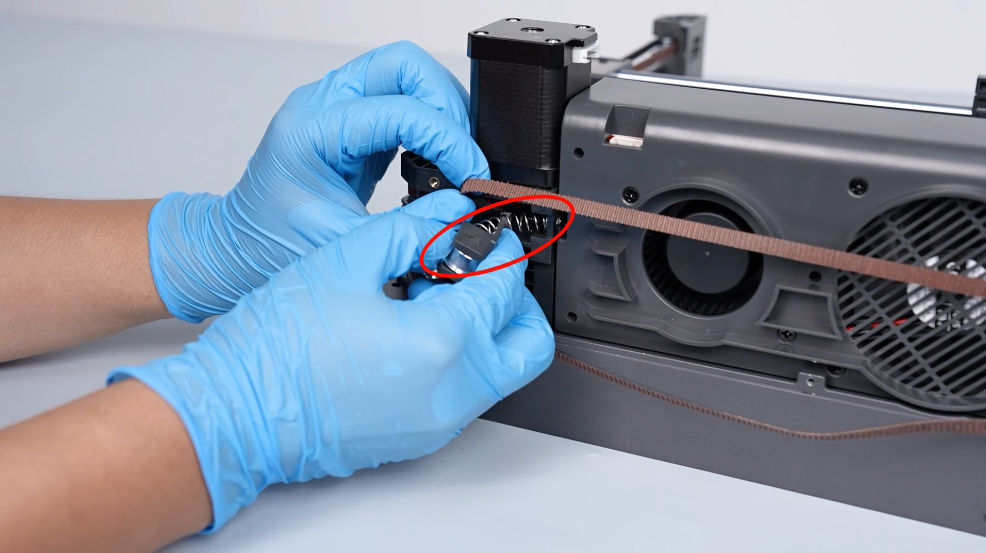
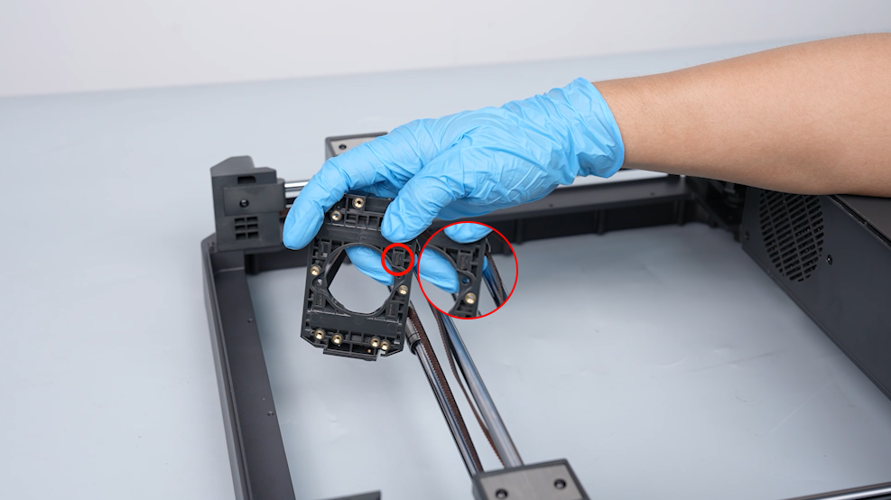
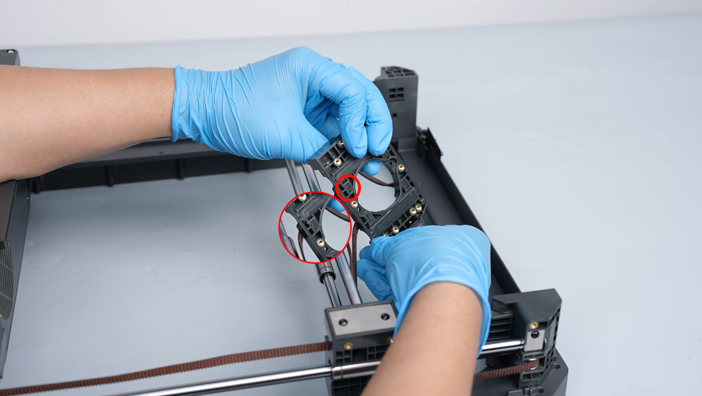
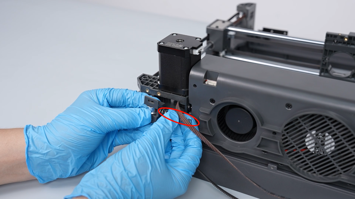
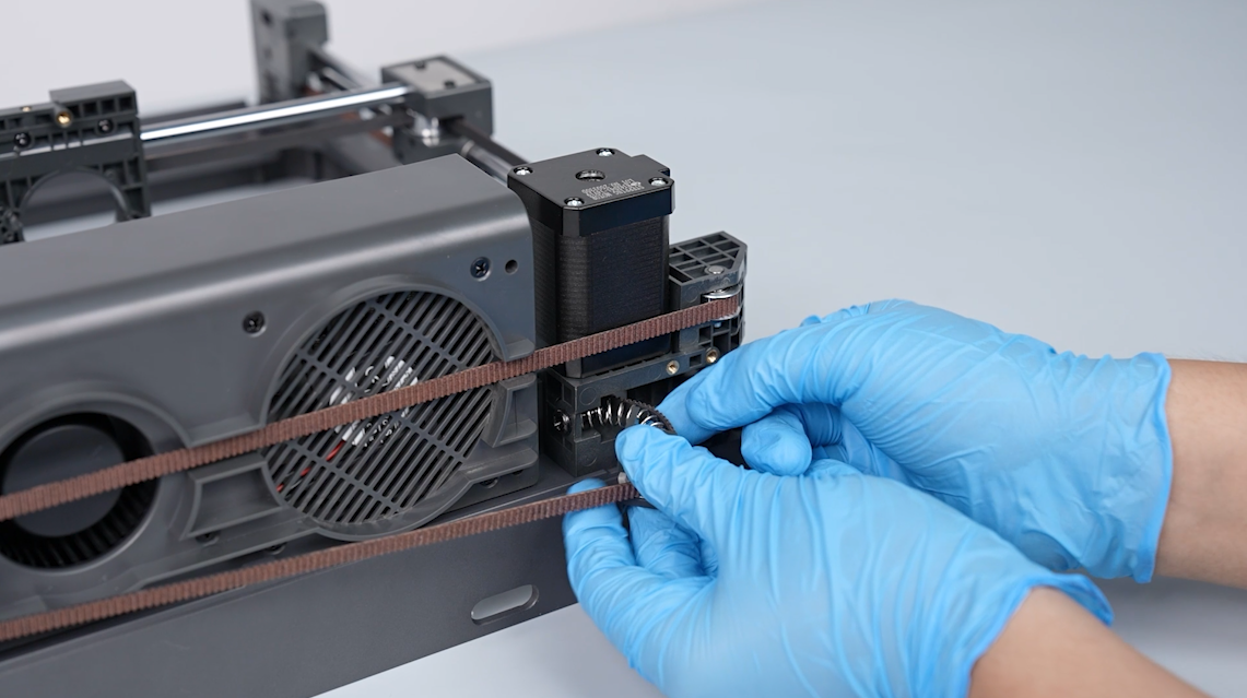
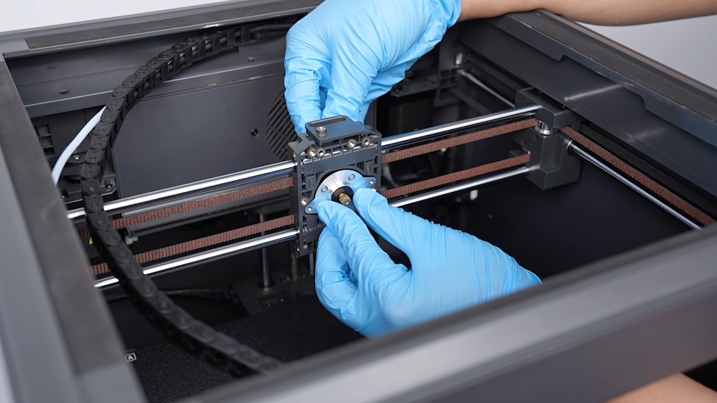
- Pass the front of the timing belt through the installation hole of the fixing block of the belt. Prepare the belt clip and put it in front of the timing belt. Press the clip to install the belt in original place.
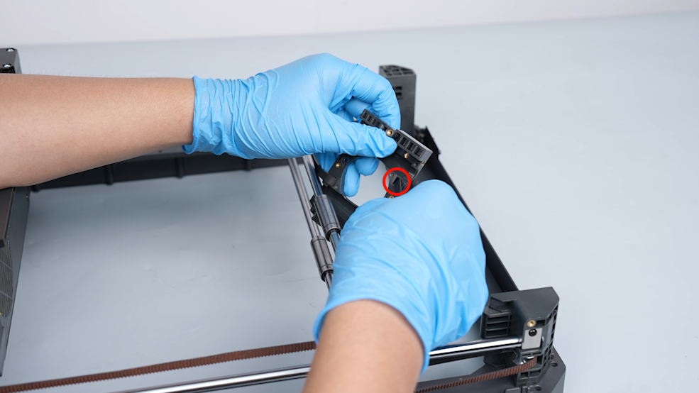
- Install the terminal of the timing belt on the fixing port.
¶ Replace the other timing belt
Replace the other timing belt in the same way.
¶ Install the components securing the timing belt
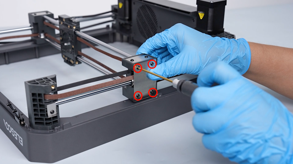
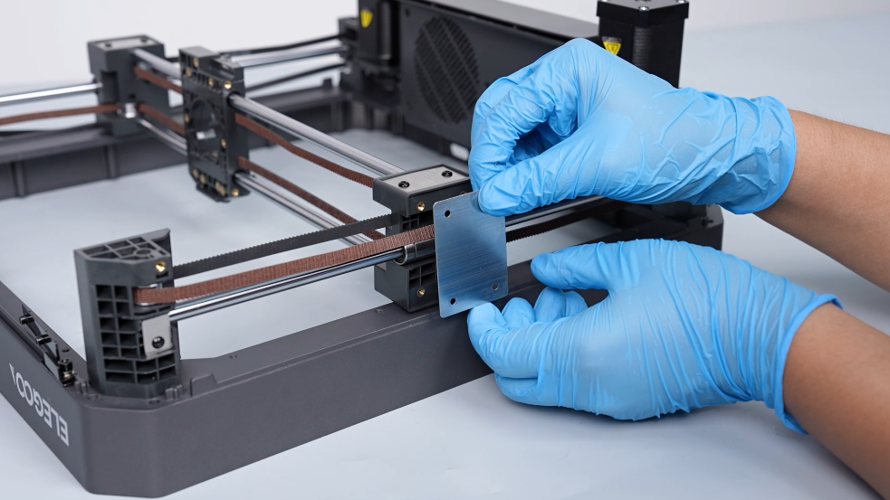
- Put the belt pressure plate in the installation position by aligning it with the screw holes and the bearing groove. Tighten the 4 screws securing belt pressure plate using a 2.0 mm Allen key.
- Put the timing belt in the groove of the fixing block of the X-axis plain shaft. Put the metal plate for fixing at the outside of the fixing block of the X-axis plain shaft in the installation position. Tighten the 4 screws securing the metal plate for fixing using a 2.0 mm Allen key.
- Install the sheet metal of the X-axis plain shaft at the other side in the same way.
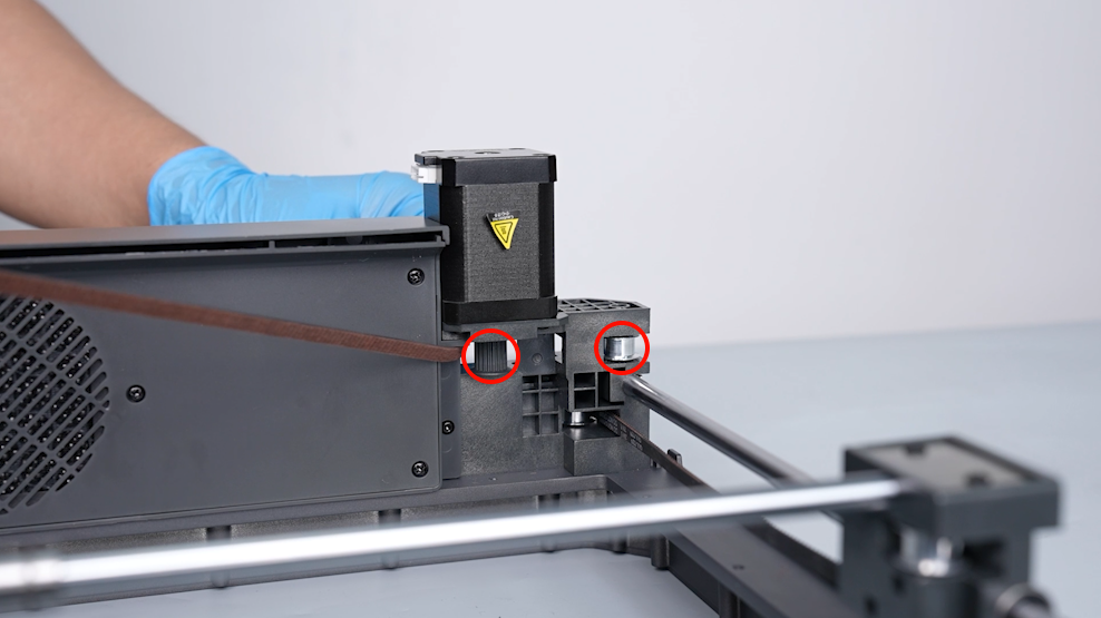
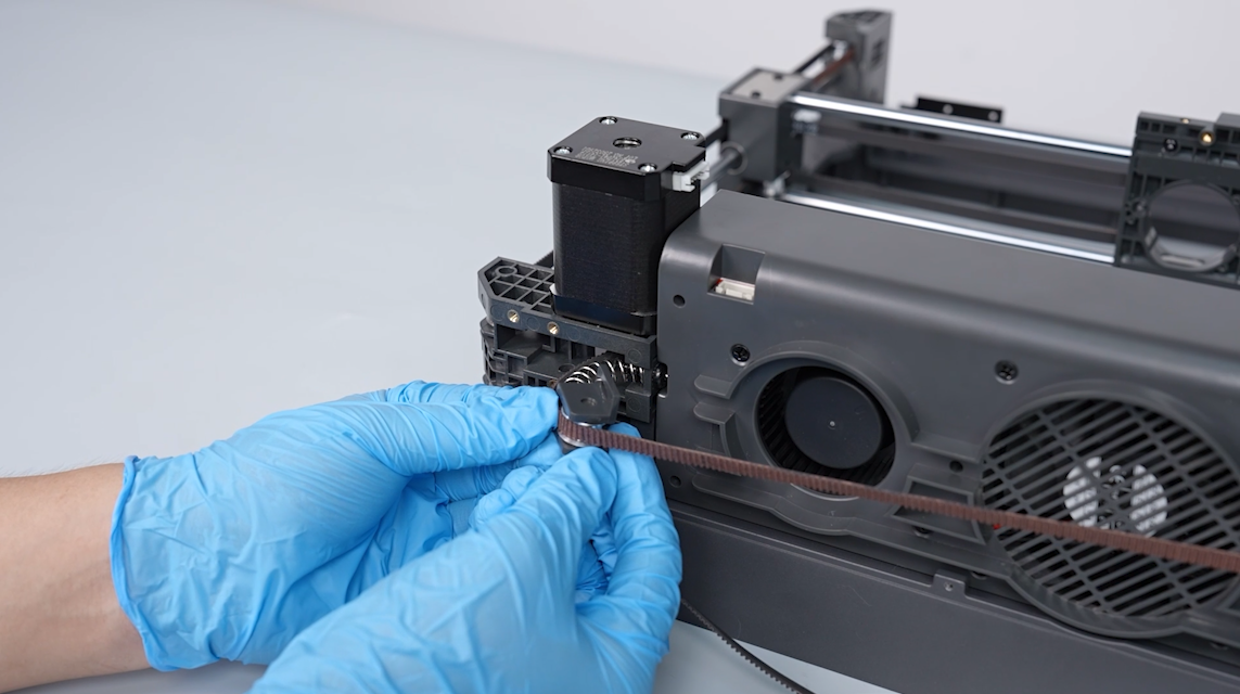
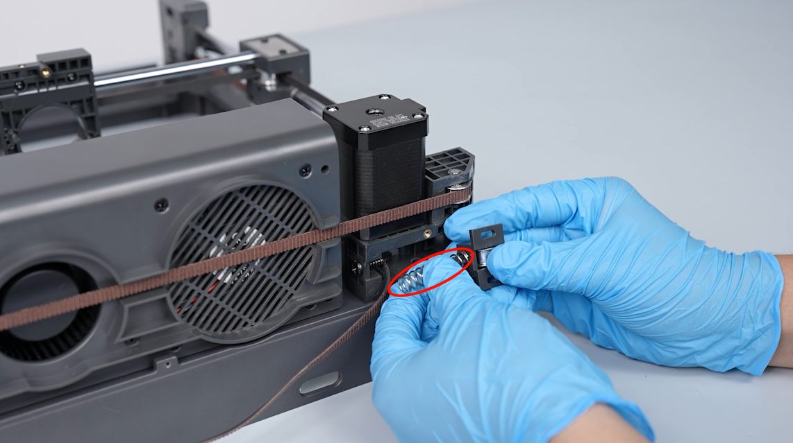
- Install the spring on the fixing column of the belt tensioner. Put the spring in the installation position by aligning it with the screw. Compress the spring to install the timing belt on the idler pulley of the belt tensioner.
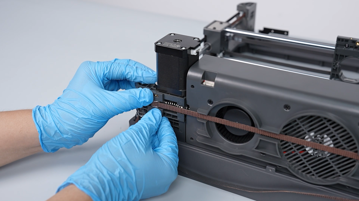
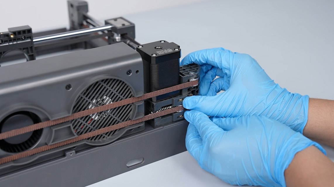
- Press the belt tensioner, then put it in the installation position by aligning it with the screw holes. Tighten the 2 screws securing the belt tensioner by third-fourths of screws' depth using a 2.0 mm Allen key.
- Install the belt tensioner on the other side in the same way.
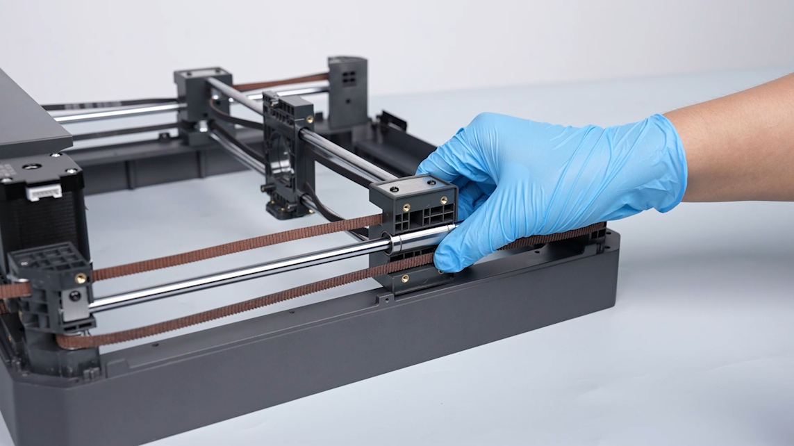
- Hold the print head and move it back and forth steadily. The belt tension can be adjusted automatically since that the belt tensioner is spring-loaded.
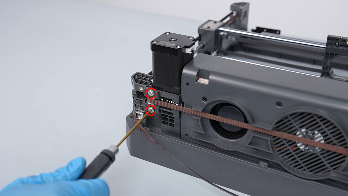
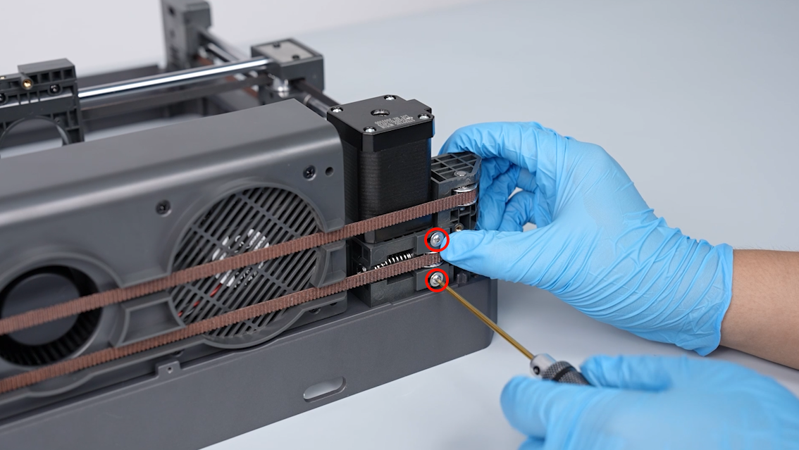
- Tighten the 2 screws securing the belt tensioner using a 2.0 mm Allen key.
¶ Install the top frame
- Put the top metal frame in the installation position by aligning it with the four pillars.
Note: Make sure the back side of the frame is aligned with the four pillars.
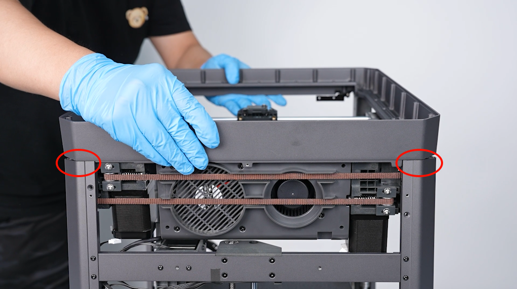
- Pull the pillar and put the top metal frame in the installation position.
- Tighten the 6 screws at the two sides of the printer and the metal frame of the upper part of the back pillars using a 2.0 mm Allen key.
- Tighten the 8 screws securing the top metal frame using a 3.0 mm Allen key.
- Prepare the plastic enclosure of the top frame and insert into the ribbon cables of the strip light.
- Put the connection cable of the print head into the plastic enclosure. Tighten the 2 screws securing the lower part of the plastic enclosure.
- Organize the connection cable of the print head and put it in the groove. Put the plastic enclosure in the installation position by aligning it with groove.
- Tighten the 7 screws securing the top frame of the plastic enclosure using a 2.0 mm Allen key.
Note: Secured in front are two short screws.
- Tighten the 6 screws securing the top frame of the plastic enclosure using a 2.0 mm Allen key.
- Paste the 4 pieces of shock-absorbing foam to the top frame of the enclosure.
Note: If the adhesion is poor, reapply the double-sided tape to the shock-absorbing foam.
- Insert the ribbon cables of the two print head motors.
- Insert the ribbon cables of the adapter board port of auxiliary cooling fan.
¶ Install the front, back, left and right covers and the top metal frame
- Put the front glass cover in the installation position by aligning it with the screw holes. Tighten the 4 screws securing the door using a 2.0 mm Allen key.
- Put the right-side cover in the installation position by aligning it with the screw holes. Tighten the 8 screws securing the right-side cover using a 2.0 mm Allen key.
- Put the back cover in the installation position by aligning it with the screw holes. Tighten the 12 screws securing the back cover using a 2.0 mm Allen key.
Note: Screw holes labeled by the red circle are M3*4, while screw holes labeled by the yellow circle are M3*8.
- Put the left-side cover in the installation position by aligning it with the screw holes. Tighten the 8 screws securing the left-side cover using a 2.0 mm Allen key.
- Put the multi-color connector in the installation position by aligning it with the screw holes. Tighten the 2 screws securing the multi-color connector using a 2.0 mm Allen key.
- Pass the ribbon cables of the filament runout detection through the hole. Inser the ribbon cables into the port of the filament runout detection.
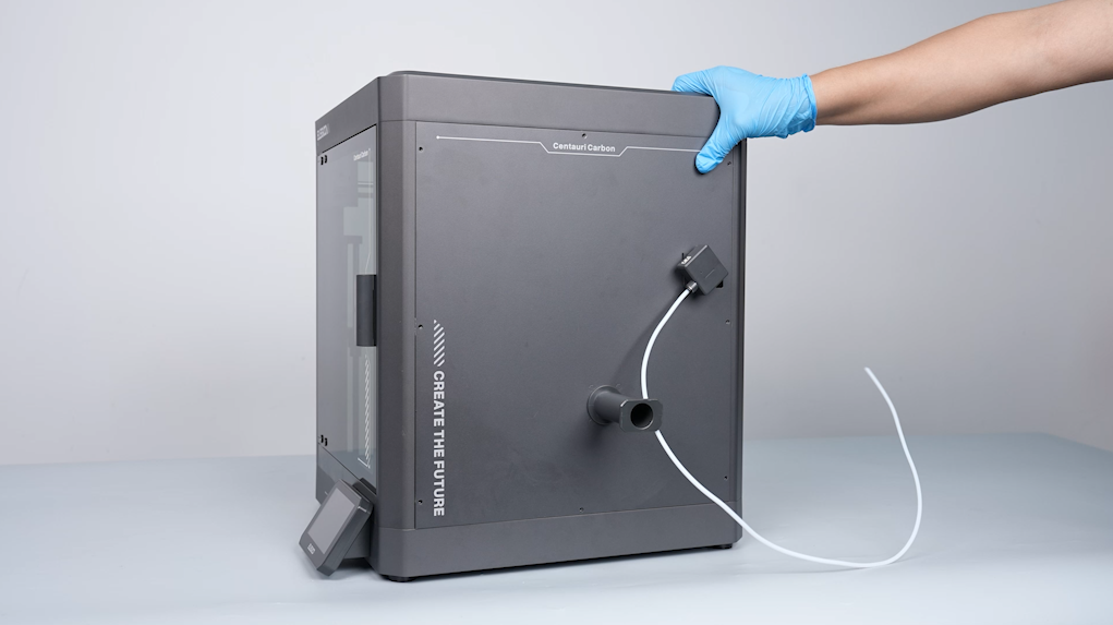
- Pass the PTFE tube through the filament hole at the back of the printer. Clamp the front of the PTFE tube and pull the tube out.
- Press the PTFE pipe into the tank chain from the terminal of the chain. Install the PTEE pipe to the one-third from the end of the tank chain.
- Tighten the 2 screws securing the cable chain terminal using a 2.0 mm Allen key.
¶ Install the print head assembly
- Prepare the extruder motor. Rotate the motor and put it in the installation position. Tighten the 2 screws securing the extruder motor using a 2.0 mm Allen key.
- Put the PCB of the print head in the installation position by aligning it with the screw holes. Use a Phillips screwdriver to tighten the 3 screws securing the PCB of the print head.
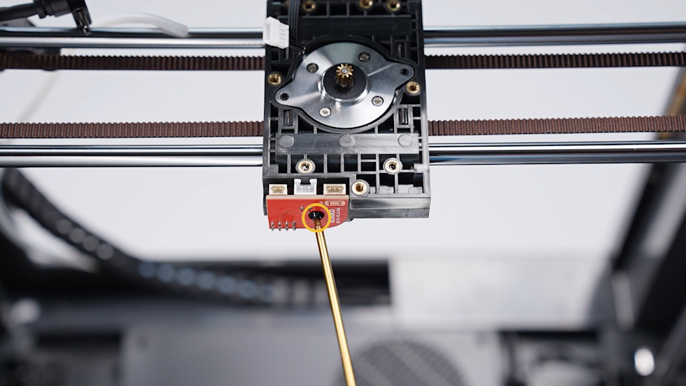
- Insert the heating PCB into the PCB of the print head by aligning it with the ribbon cable pins. Tighten the screw securing heating PCB using a 2.0 mm Allen key.
- Insert the ribbon cables of the model cooling fan into the clip. Insert the ribbon cables of the extruder motor and the model cooling fan into the port of the PCB of the print head.
- Prepare the back cover of the print head. Put it in the installation position by aligning it with the screw holes. Tighten the 3 screws securing the back cover of the print head using a 2.0 mm Allen key.
- Put the font part of the cable chain of the print head in the installation position by aligning it with the screw holes. Tighten the screw securing the the font part using a 2.5 mm Allen key.
- Insert the connection cable port of the print head. Tighten the 2 screws securing the connection cable port of the print head using a 1.5 mm Allen key.
- Prepare the new heat break cooling fan assembly and put it in the installation position by aligning it with the screw holes. Tighten the screw securing the heat break cooling fan assembly using a 2.0 mm Allen key. Insert the ribbon cables of the heat break cooling fan into the adapter board port.
- Prepare the new gear box of the extruder and the nozzle assembly. Put them in the installation position by aligning them with the screw holes. Tighten the 4 screws securing the gear box of the extruder assembly using a 2.0 mm Allen key.
- Insert the ribbon cables of the ceramic heating plate and the thermistor into the port of the adapter board.
- Insert the PTFE tube into the connector. Put the middle housing of the print head in the installation position by aligning it with the reserved groove of the cutter lever and the screw holes. Tighten the 4 screws using a 2.0 mm Allen key.
- Insert the port of the ribbon cables of the model cooling fan. Organize the ribbon cables of the model cooling fan. Put the front cover of the printing head in the installation position by aligning it positioning holes.
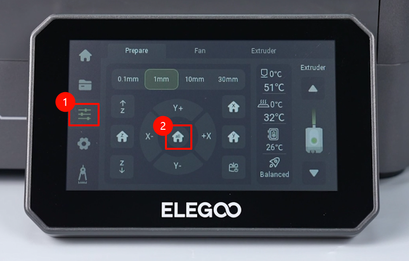
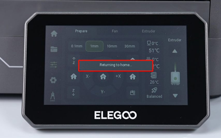
- Power on the printer. Navigate to "Prepare - all" on the touchscreen. The print head strats homing process.
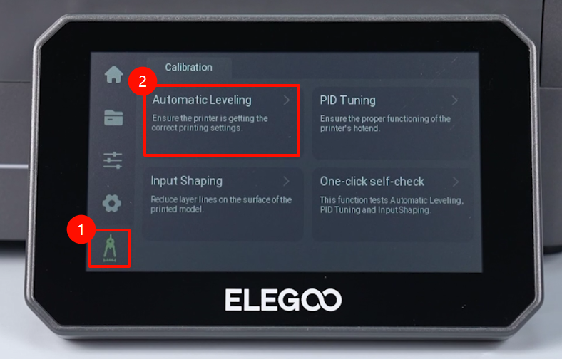
- Navigate to "Level - Confirm" on the touchscreen. The printer is ready for use after it is re-leveled.