¶ Tools and Materials
- A 2.0 mm Allen key
- A 2.5 mm Allen key
- A Phillips screwdriver
- A pair of diagonal pliers
- Cable ties
- A new nozzle assembly


¶ Tutorial Video
¶ Instruction
¶ Remove the old heated bed assembly
- Power off the printer and unplug the power cord.
- Put the printer on its side. Loosen the 10 screws securing the bottom cover of the printer using a 2.0 mm Allen ke. Remove the printer.
Note: Keep the glass door closed to prevent it from falling during the process.

- Unplug the adapter cable of the heated bed leveling sensor circuit board and the "BED-T" (heated bed thermistor) ribbon cable on the motherboard.

- Cut off the two pieces of cable tie securing ribbon cables on the cable holder using a pair of diagonal pliers.


- Loosen the "OUTPUT" port securing the 3 ribbon cables on the heated bed control board using a Phillips screwdriver.
Note: Organize the ribbon cables.

- Take out the main cable of the heated bed from its hole inside the printer.


- Cut off 2 cable ties securing the main cable using a pair of diagonal pliers.


- Loosen the 4 long screws fixed below the heated bed using a 2.5 mm Allen key.
Note: Loosen half of the long screws, then unscrew them as there are springs inside the heated bed.

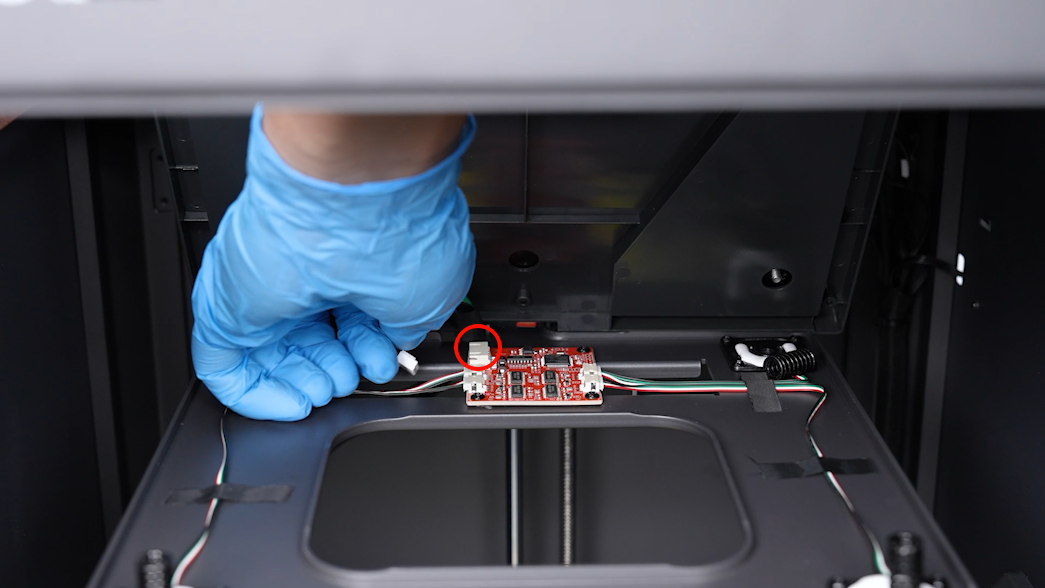
- Lift the heated bed. Unplug the port of adapter cable on the circuit board of the heated bed leveling sensor.

- Remove the old heated bed assembly and the 4 springs.


¶ Install the new heated bed assembly
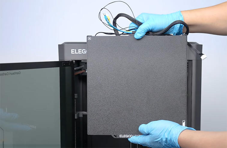
- Prepare the new heated bed assembly. Organize the ribbon cables. Stand the heated bed on its holder's back edge.


- Insert the adapter cable of the heated bed leveling sensor into the circuit board port.


- Put the 4 springs in the installation position by aligning it with the screw holes. Put the heated bed in the installation position by aligning it with the screw holes.


- Pass the 4 long screws below the heated bed. The long screws should pass the center of the spring and turn slightly to secure them. Secure half of the four long screws using a 2.5 mm Allen key. Then, tighten them completely.


- Put the ribbon cables of the hotbed into the groove beside the heated bed holder. Use a cable tie to secure the main cable.
Note: Leave enough slack in the main cable to prevent tension when securing the ribbon cable below. Otherwise, the hotbed's movement may be impacted.


- Pass the main cable of the heated bed through its hole to the printer's bottom.


- Insert the three heating cables of the heated bed into the "OUTPUT" port on the motherboard according to the lable information.

- Organize the ribbon cables. Insert the adapter cable of the heated bed leveling sensor circuit board and the "BED-T" (hotbed thermistor) ribbon cable into the ports on the motherboard.

- Use 2 cable ties to secure the ribbon cable on the holder.

- Put the bottom cover of the printer in the installation position by aligning it with the foot pad holes and screw holes. Use a 2.0 mm Allen key to loosen the 10 screws securing the bottom cover.

- Power on the printer. Navigate to "Function" on the touchscreen to enter the Prepare interface. Set the temperature of the heated tbed to 60 ℃.

- Observe that the heated bed heats up normally. The printer is ready for use after it is re-leveled.
