¶ Tools and Materials
- A 2.0 mm Allen key
- A 2.5 mm Allen key
- A pair of tweezers
- A new gear of the extruder

¶ Tutorial Video
Coming soon.
¶ Instruction
¶ Remove the old gear of the extruder
- Power off the printer and unplug the power cord.
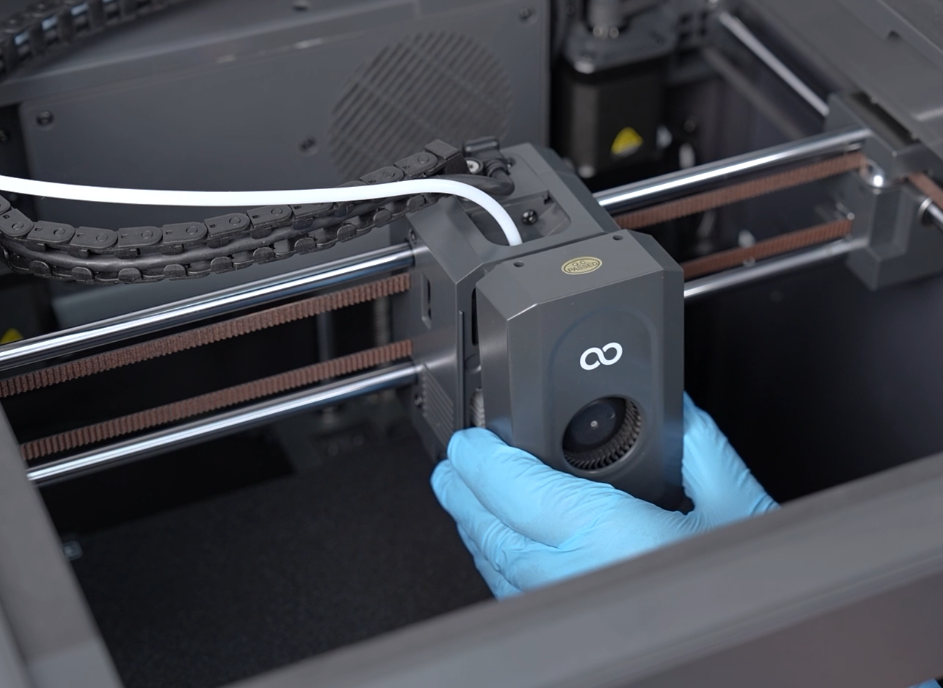
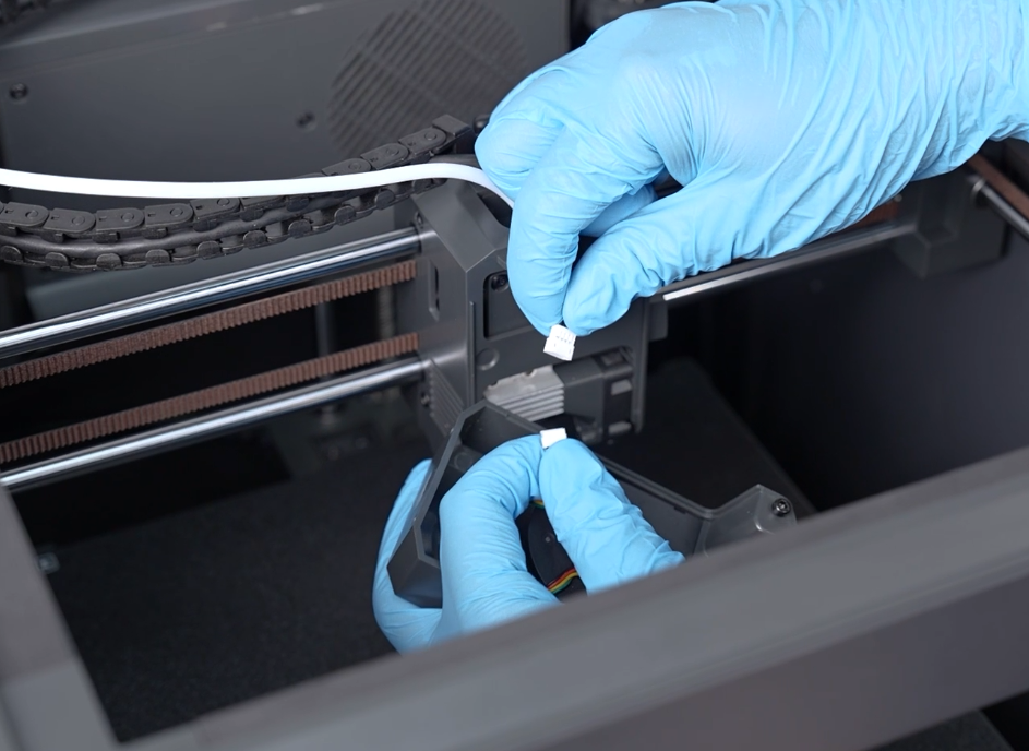
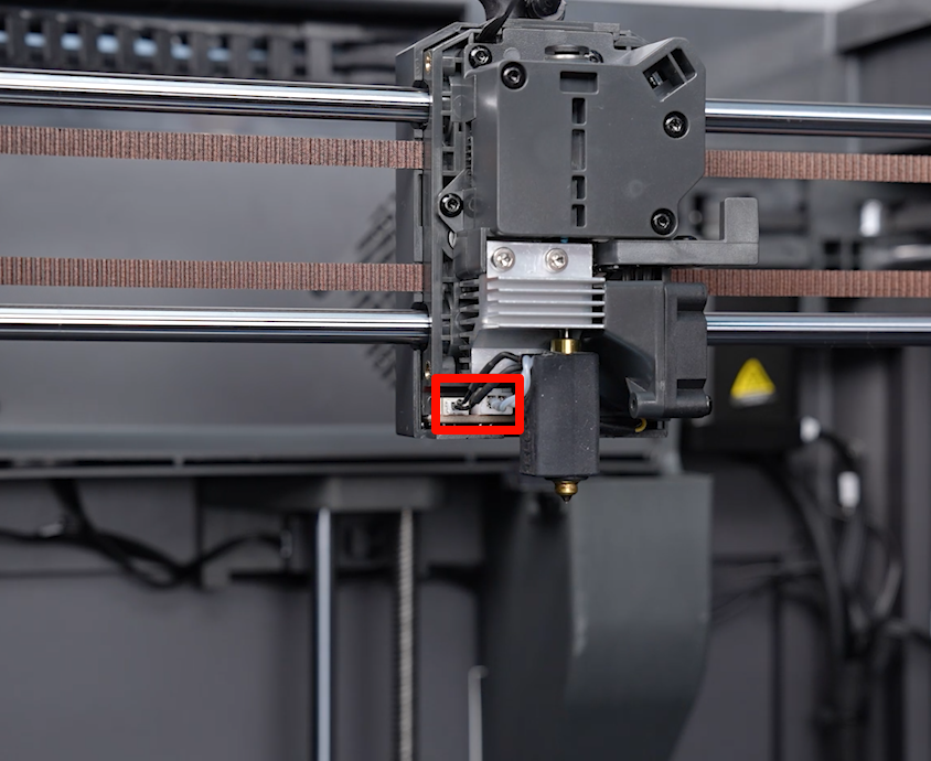
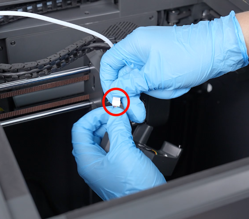
- Lift the front cover of the printing head to remove it. Unplug the port of the ribbon cables of the model cooling fan.
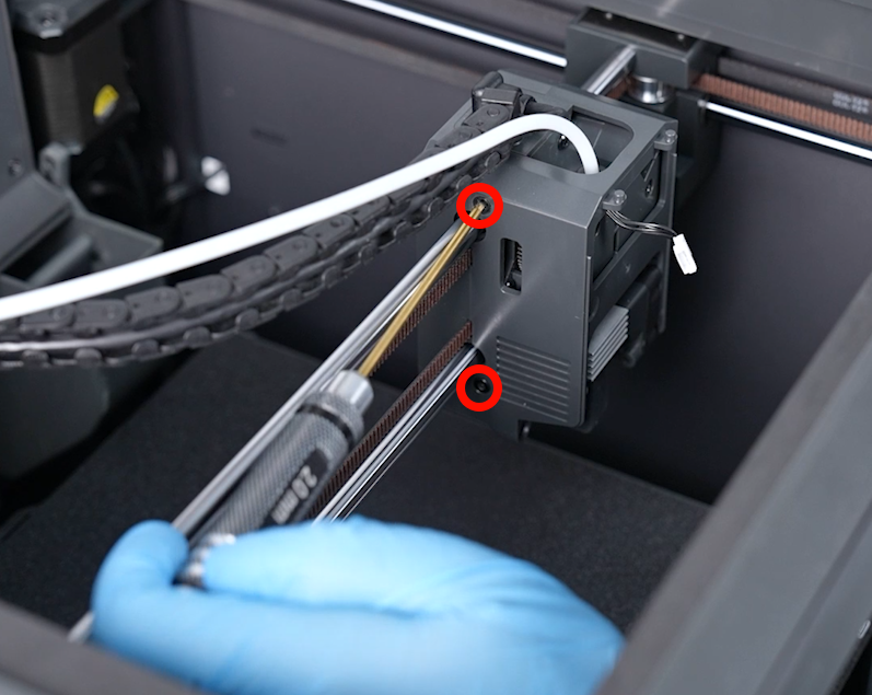
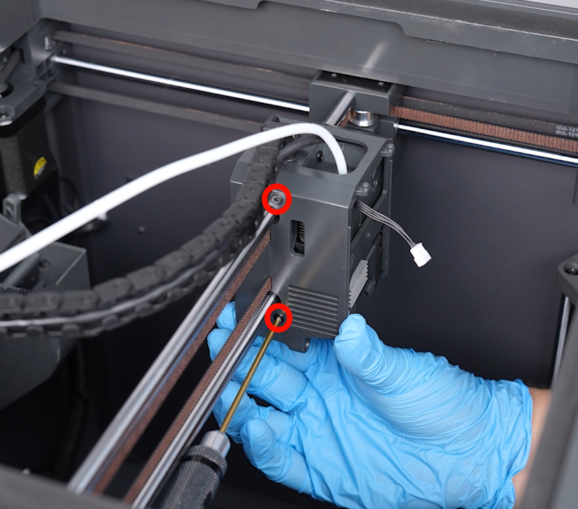
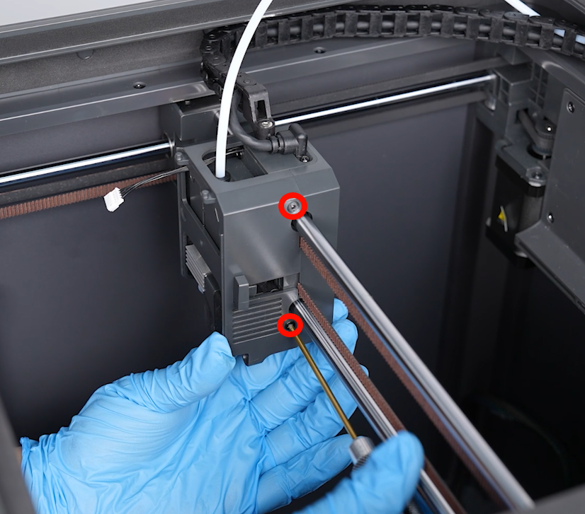
- Use a 2.0 mm Allen wrench to loosen the 4 screws securing the middle housing of the print head. Remove the middle housing from the front of the print head.
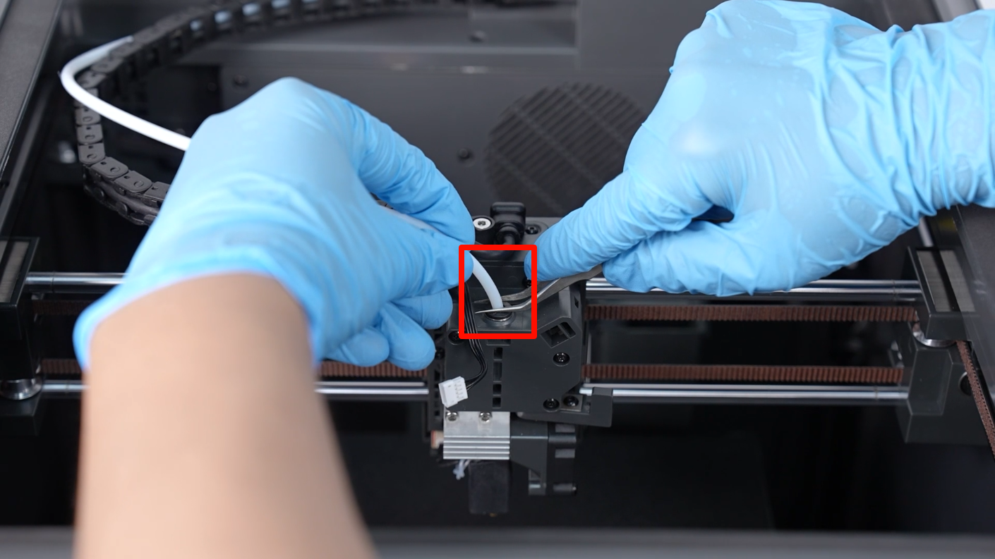
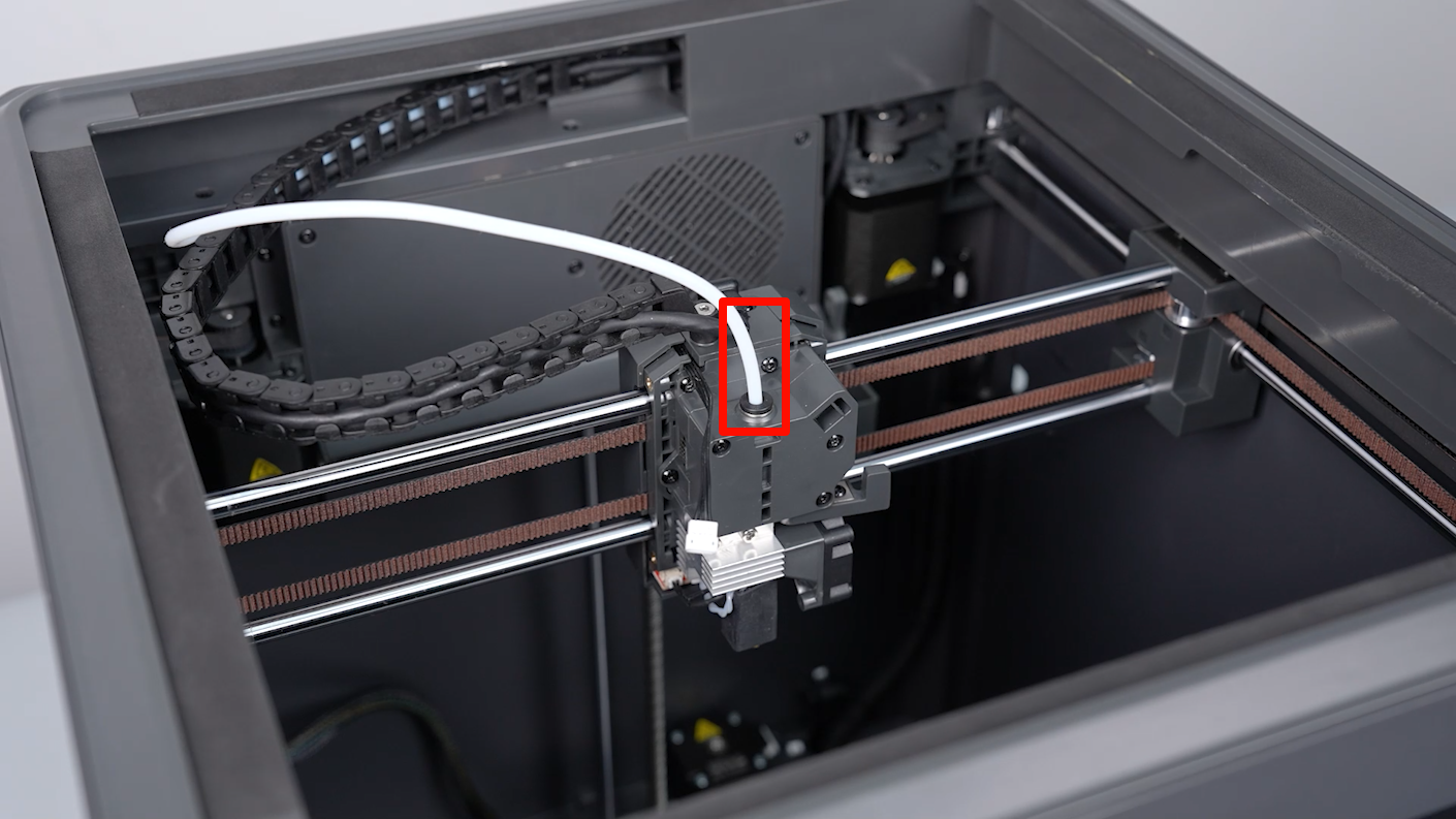
- Press downward the tablet of the connector using a pair of tweezers, then unplug the input tube.
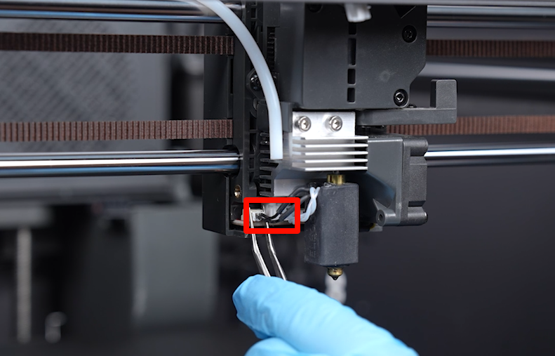
- Unplug the ribbon cables of the ceramic heating plate and the thermistor.
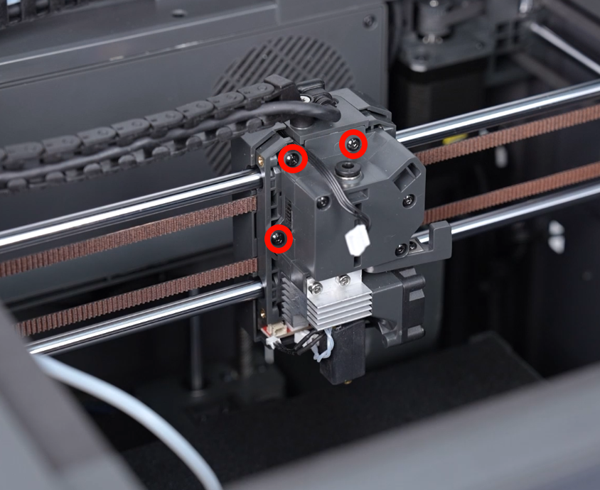
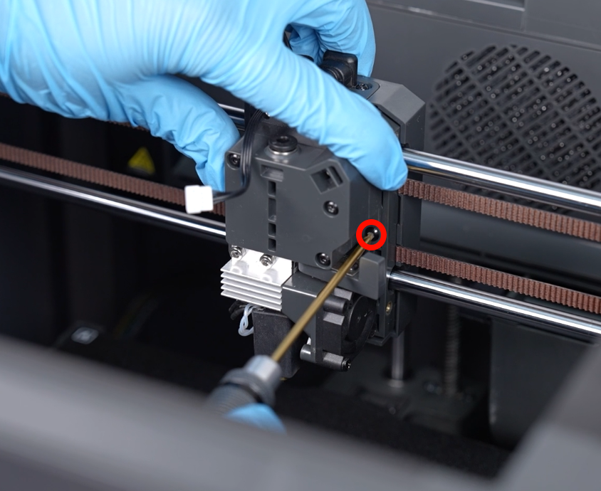
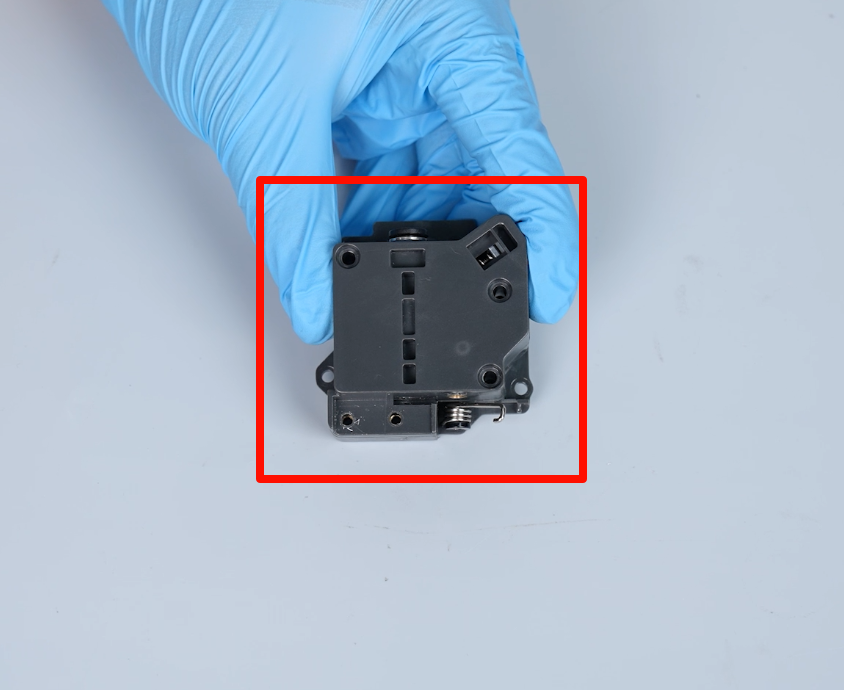
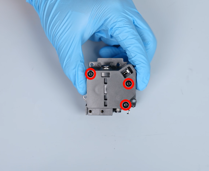
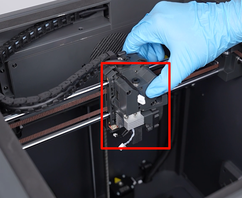
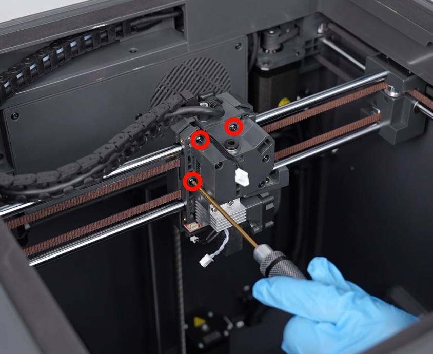
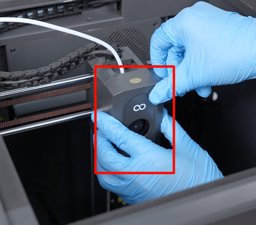
- Use a 2.0 mm Allen key to loosen the 4 screws securing the gearbox of the extruder assembly. Then, remove the gearbox of the extruder and the nozzle assembly.
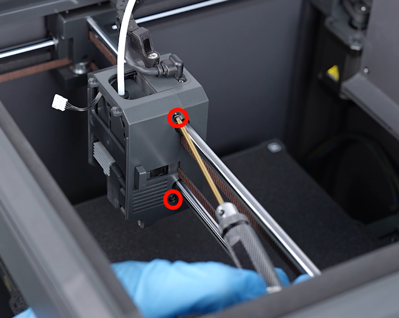
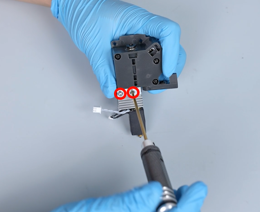
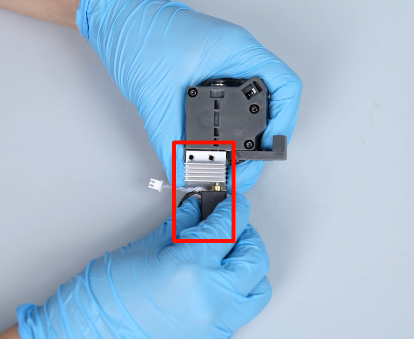
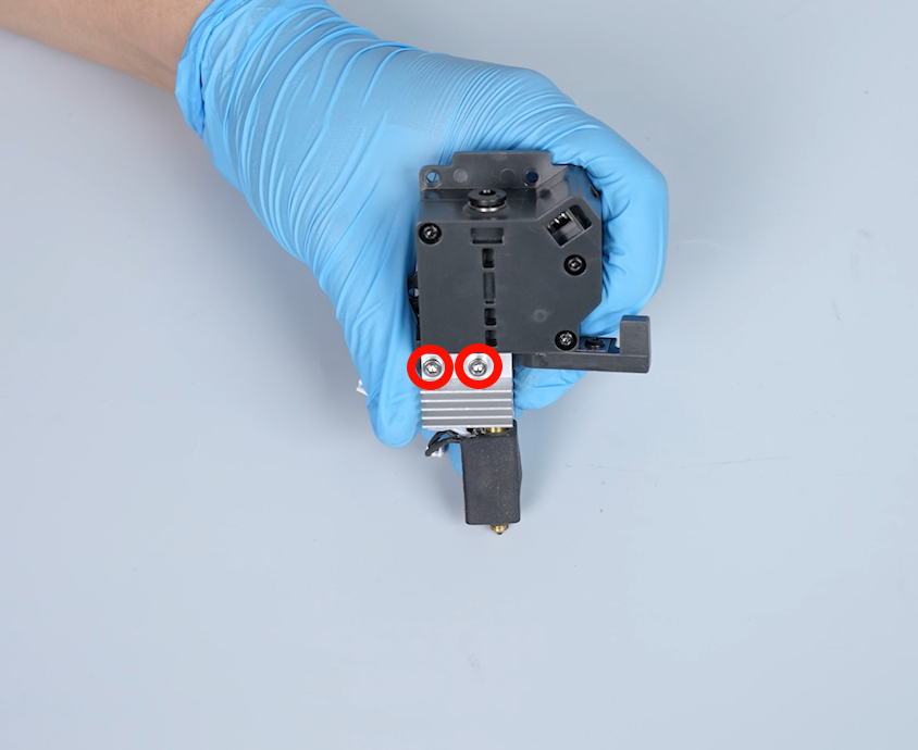
- Use a 2.5 mm Allen key to loosen the 2 screws securing the nozzle assembly, then remove the nozzle assembly.
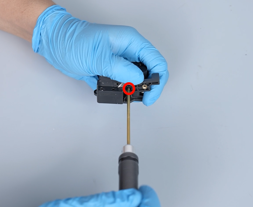
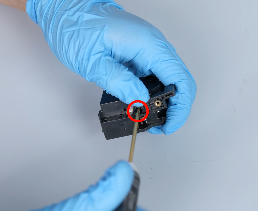
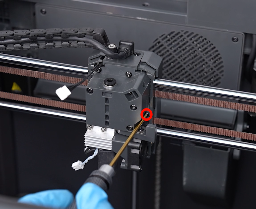
- Use a 2.0 mm Allen key to loosen the screw securing the cutter, then remove the cutter.
Note: Press down on the center of the cutter to prevent it from popping out.
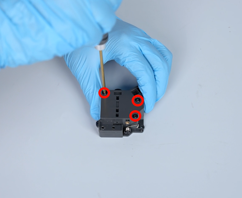
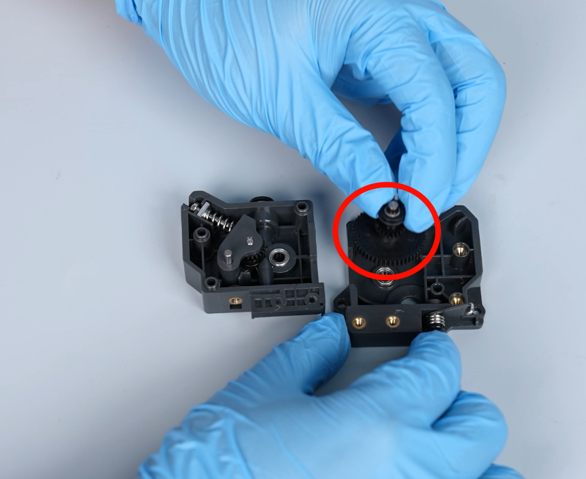
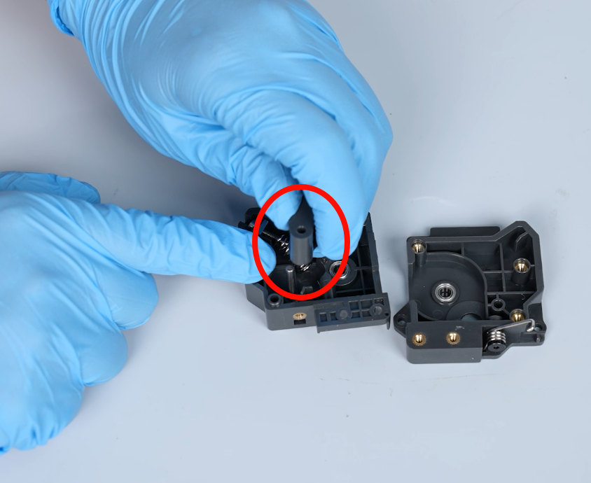
- Loosen the 3 screws securing the front cover of the extruder using a 2.0 mm Allen key, then remove the front cover.
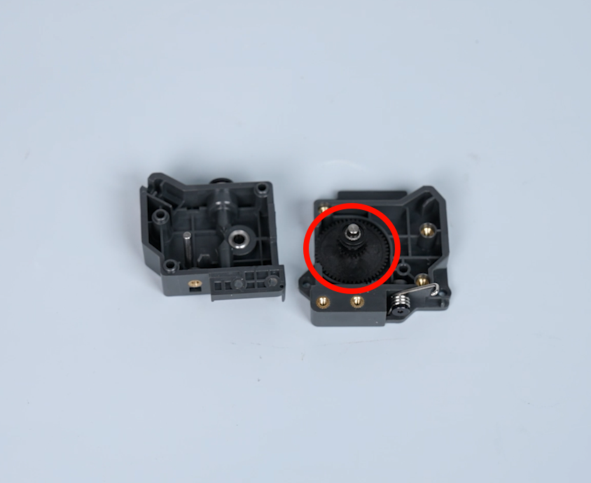
- Remove the old gear inside the extruder.
Note: Clean any foreign matter inside the extruder.
¶ Install the new gear of the extruder
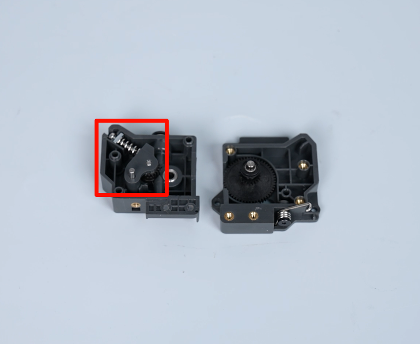
- Prepare the new gear of the extruder. Install the components inside the extruder.
- Press the front cover and back cover of the extruder and install them by aligning them with the bearing holes.
- Tighten the 3 screws securing the front cover of the extruder using a 2.0 mm Allen key.
- Put the cutter in the installation position by aligning it with the screw holes. Use a 2.0 mm Allen key to tighten the screw.
Note: Press down on the center of the cutter to prevent it from popping out.
- Put the nozzle assembly in the installation position by aligning it with the screw holes. Tighten the 2 screws securing the nozzle assembly using a 2.5 mm Allen key.
- Put the gearbox of the extruder and the nozzle assembly in the installation position by aligning them with the screw holes. Tighten the 4 screws using a 2.0 mm Allen key.
- Insert the ribbon cables of the ceramic heating plate and the thermistor into the port of the adapter board.
- Insert the input tube into the connector.
- Put the middle housing of the print head in the installation position by aligning it with the reserved groove of the cutter lever and the screw holes. Tighten the 4 screws using a 2.0 mm Allen key.
- Prepare the front cover of the print head. Insert the port of the ribbon cables of the model cooling fan. Put the front cover in the installation position by aligning it with the positioning hole.
Note: Organize the ribbon cables of the model cooling fan.
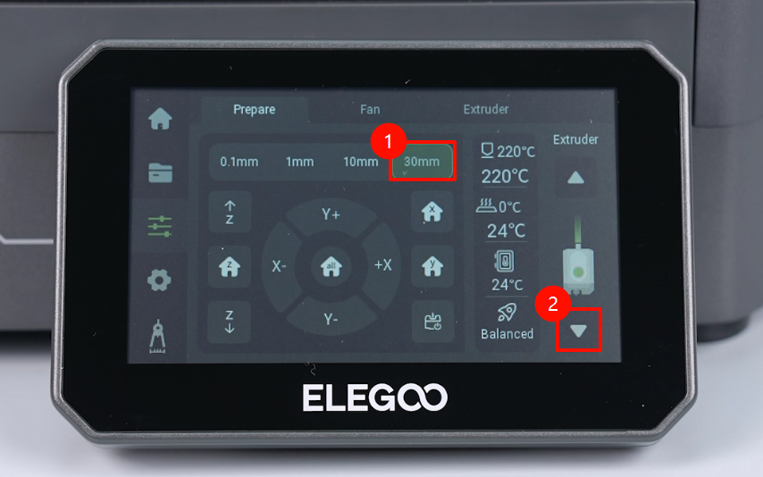
- Navigate to "Function" on the touchscreen to enter the Prepare interface. Set the temperature of the nozzle to 220 ℃.
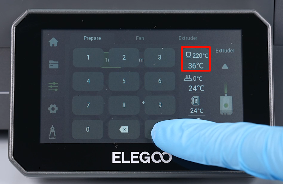
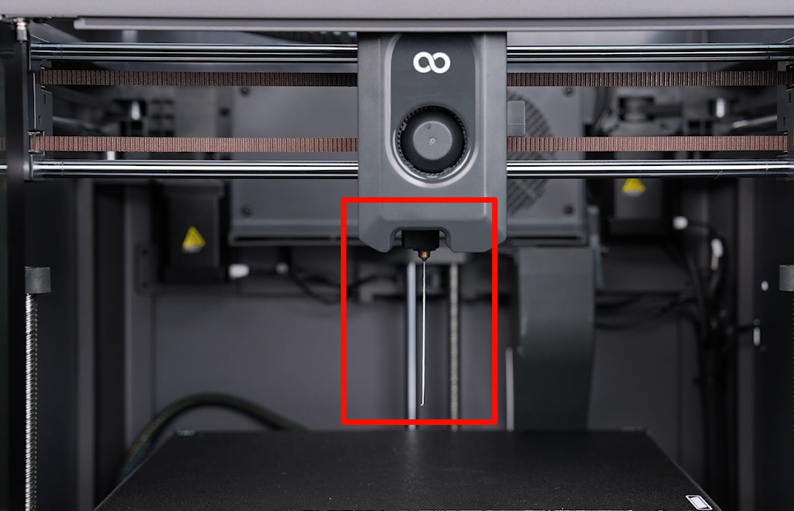
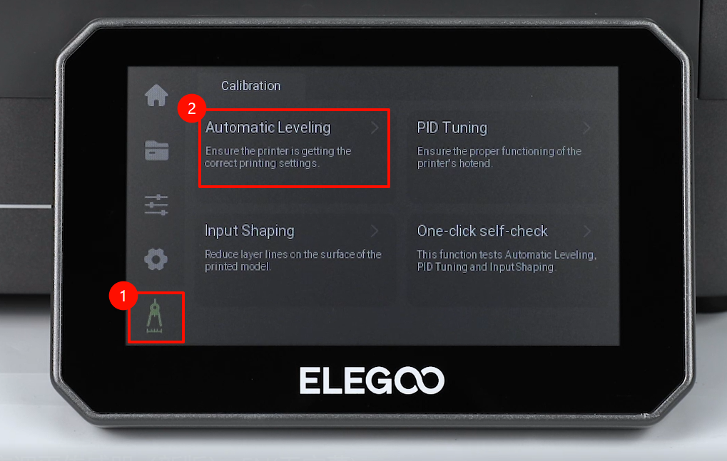
- Click "30 mm - Extrduer". Observe the filament being extruded from the nozzle. The printer can work as usual after being re-leveled.