¶ Tools and Materials
- 2.0mm Allen key x 1
- 2.5mm Allen key x 1
- A Phillips screwdriver

¶ Tutorial Video
Coming soon.
¶ Instruction
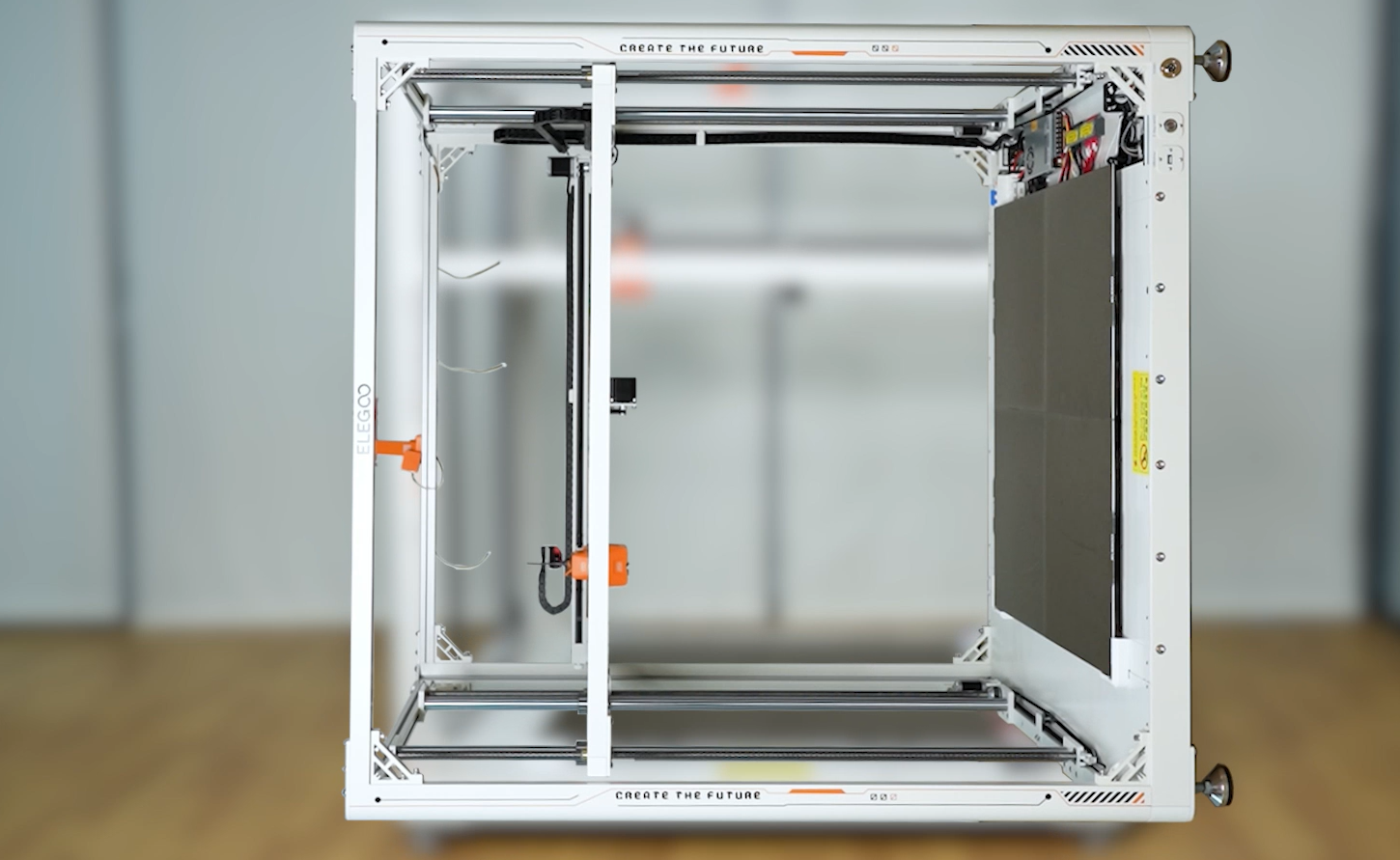
¶ Remove the old power
- Power off the printer and unplug the power cord.
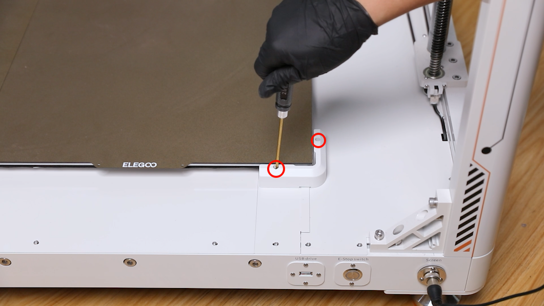
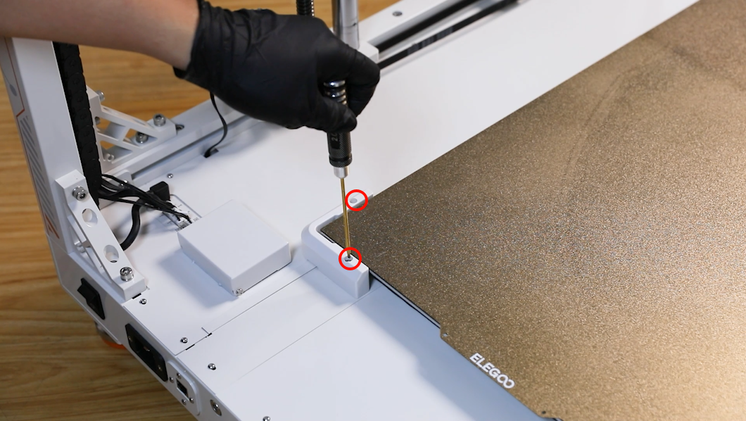
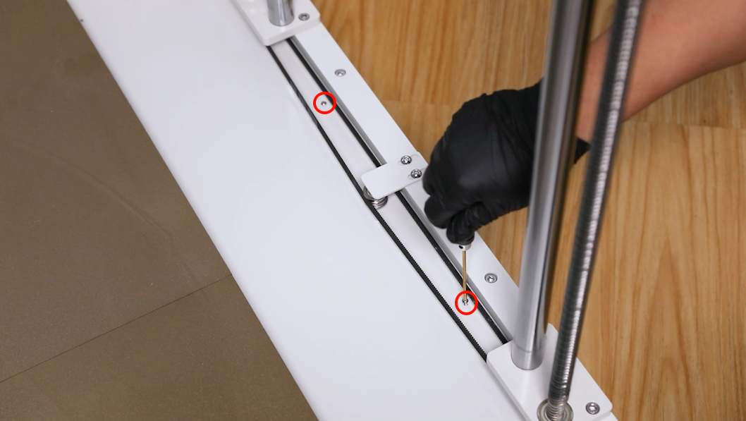
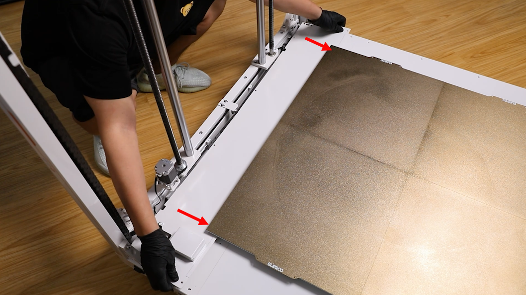
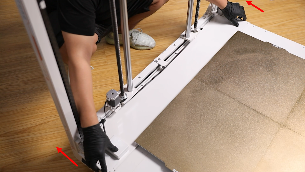
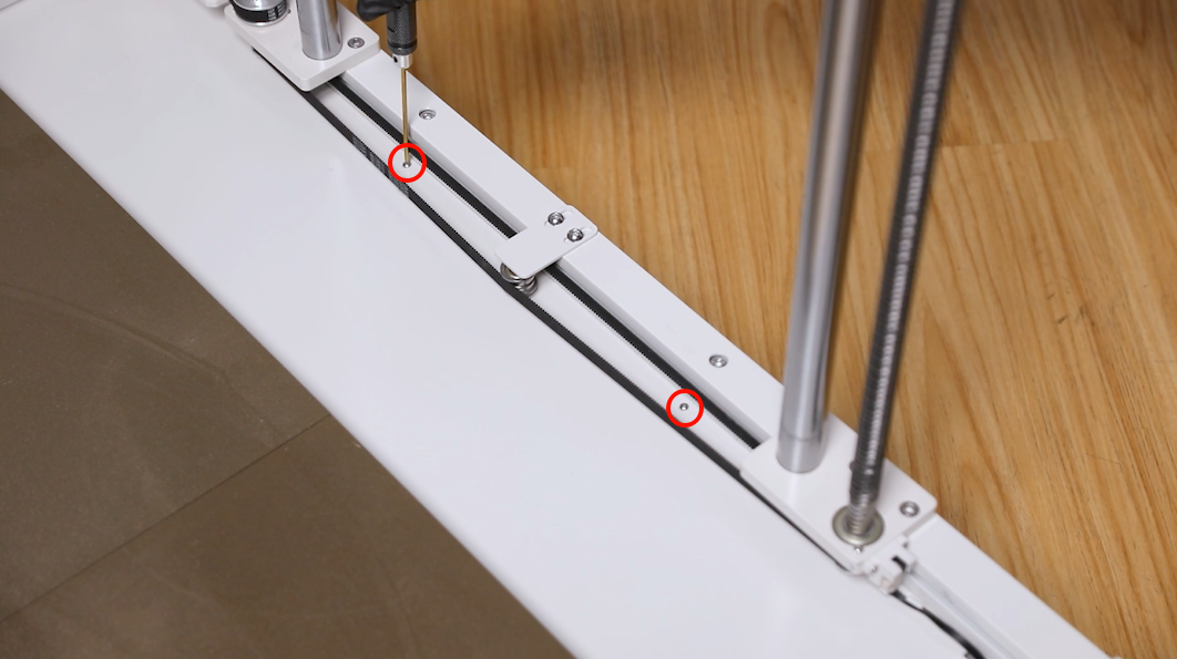
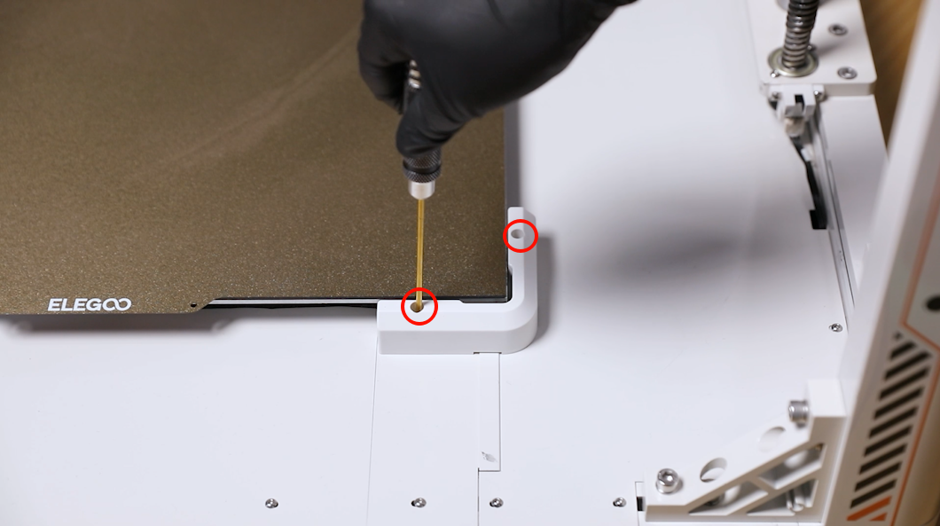
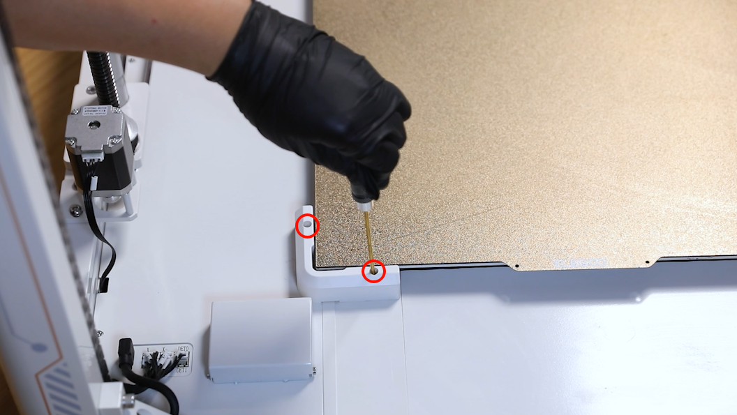
- Loosen the two screws securing the front and back PEI limiters at the right side of the printer using the 2.0 mm Allen key. Remove the PEI limiters.
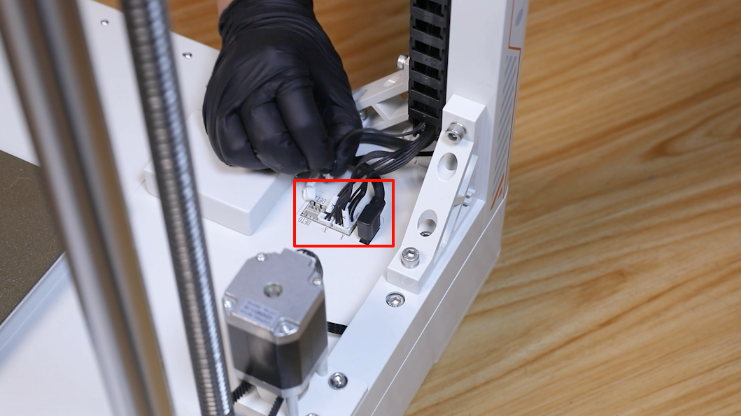
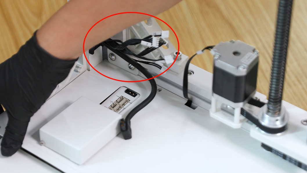
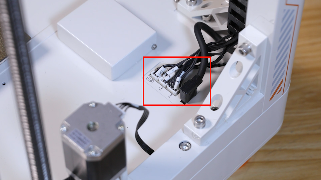
- Unplug the cables on the adapter board at the right back side of the printer.
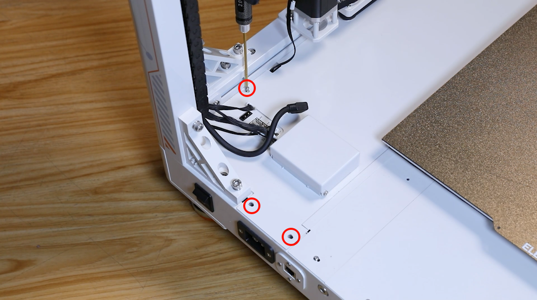
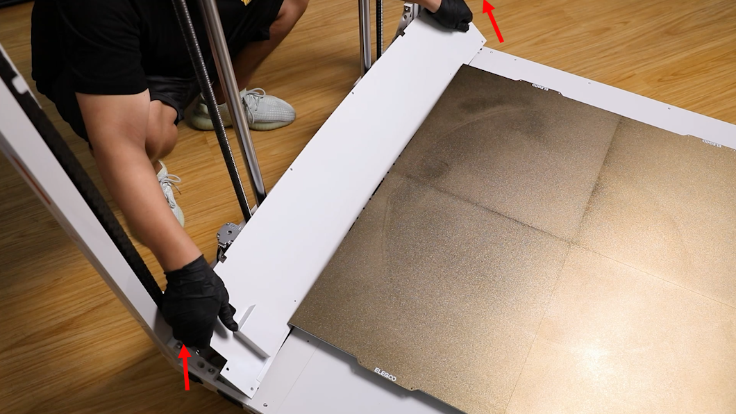
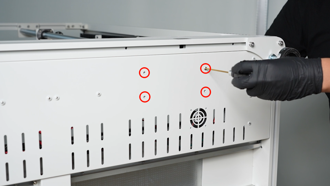
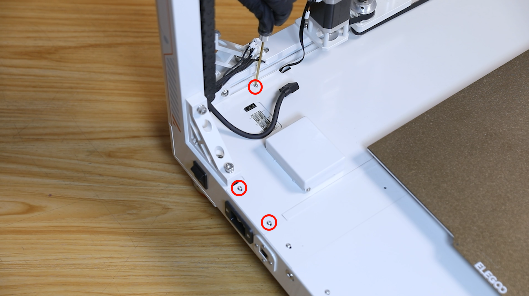
- Loosen the eight screws securing the power box cover using a 2.0 mm Allen key.
- Lift the power box cover and push it towards the heated bed. Lift the outer side of the cover and remove it.
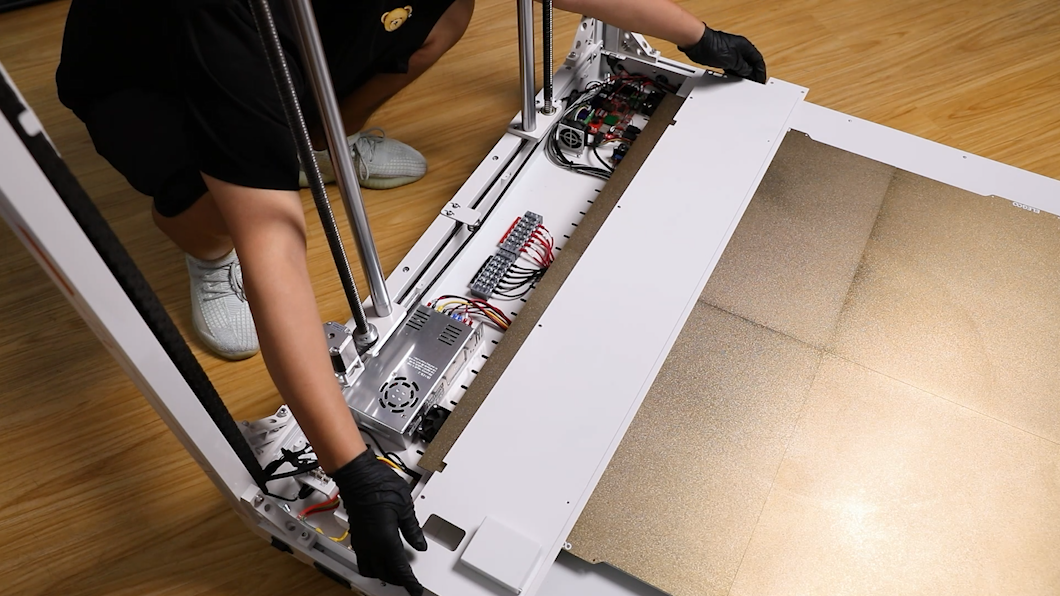
- Loosen the screws securing the power port cables using the Phillips screwdriver. Remove the cables from the power port.
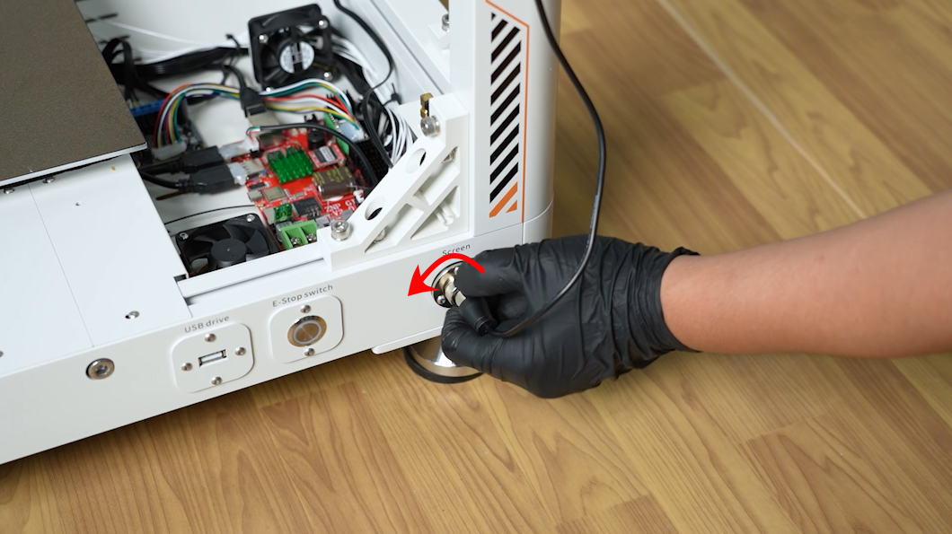
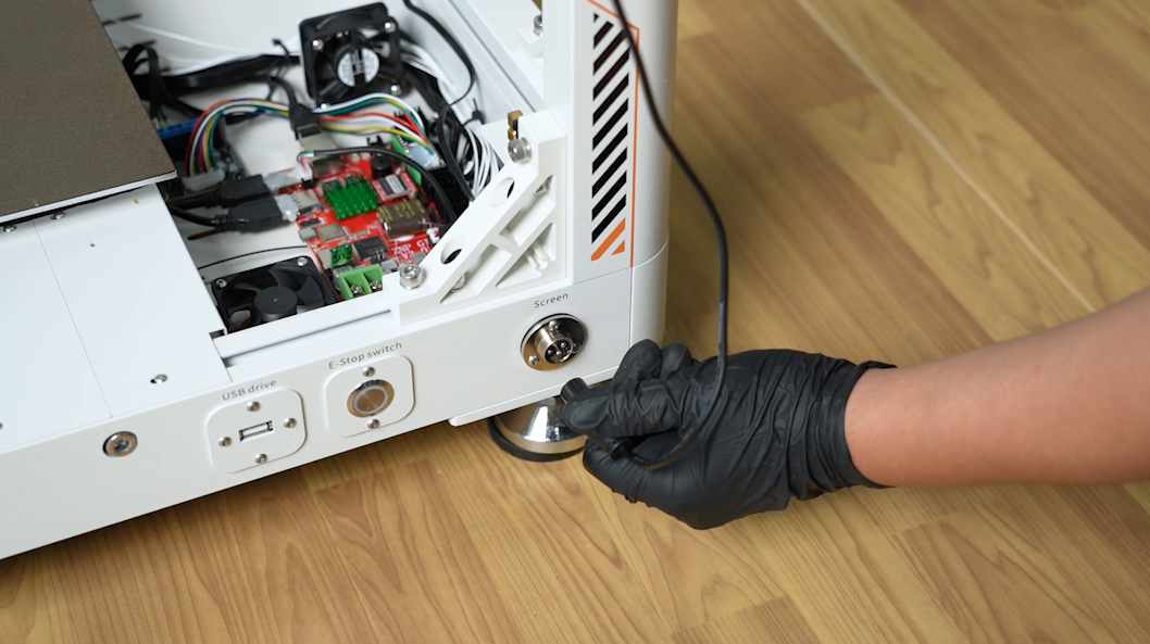
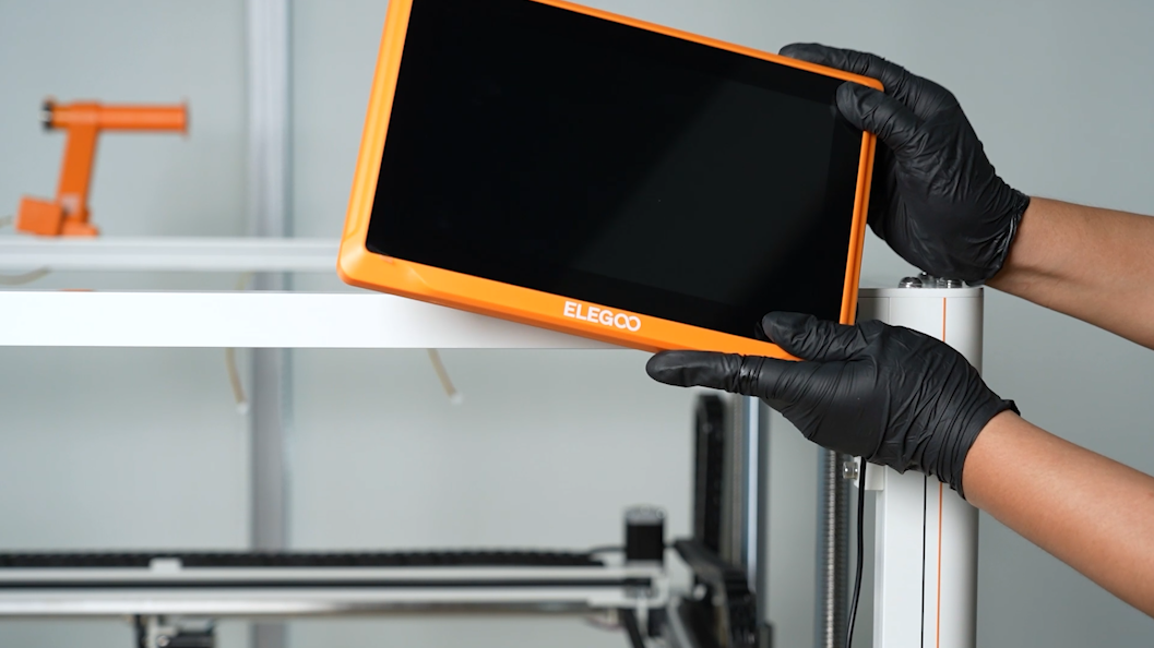
- Loosen the clip. Remove the port of the touchscreen connection cable. Remove the touchscreen.
NOTE: Remove all parts on the printer to prevent from falling.
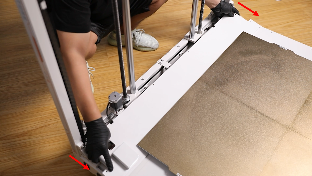
- Put the printer on its side.
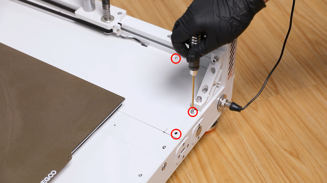
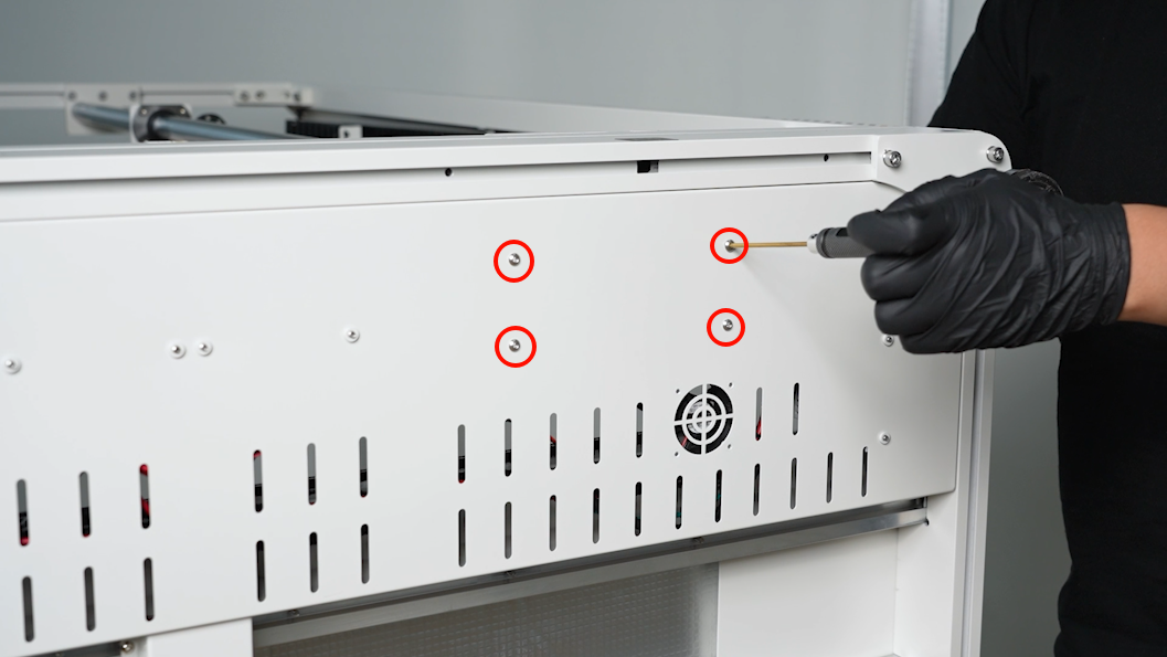
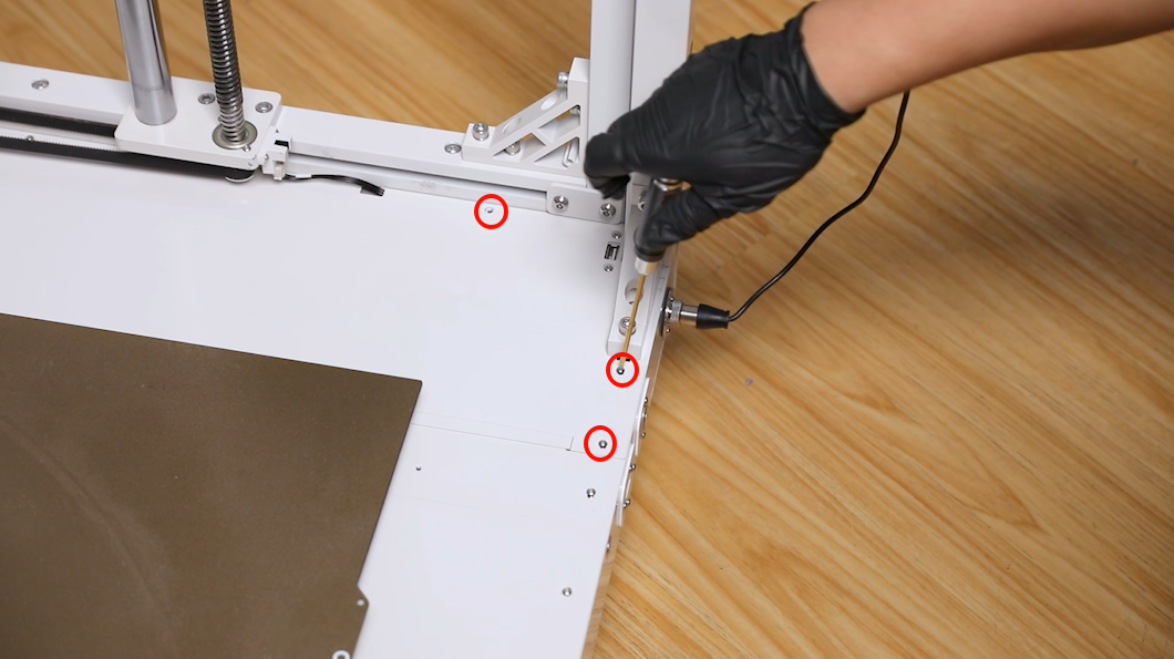
- Loosen the 4 screws securing the lens shade at the bottom of the printer using a 2.5 mm Allen key. Remove the old power.
¶ Install the new power
- Prepare the new power. Align it with the screw holes and put it in the installation position.
NOTE: Organize the cables to prevent them being pressed.
- Tighten the four screws securing the power using the 2.5 mm Allen key.
- Restore the printer's normal orientation.
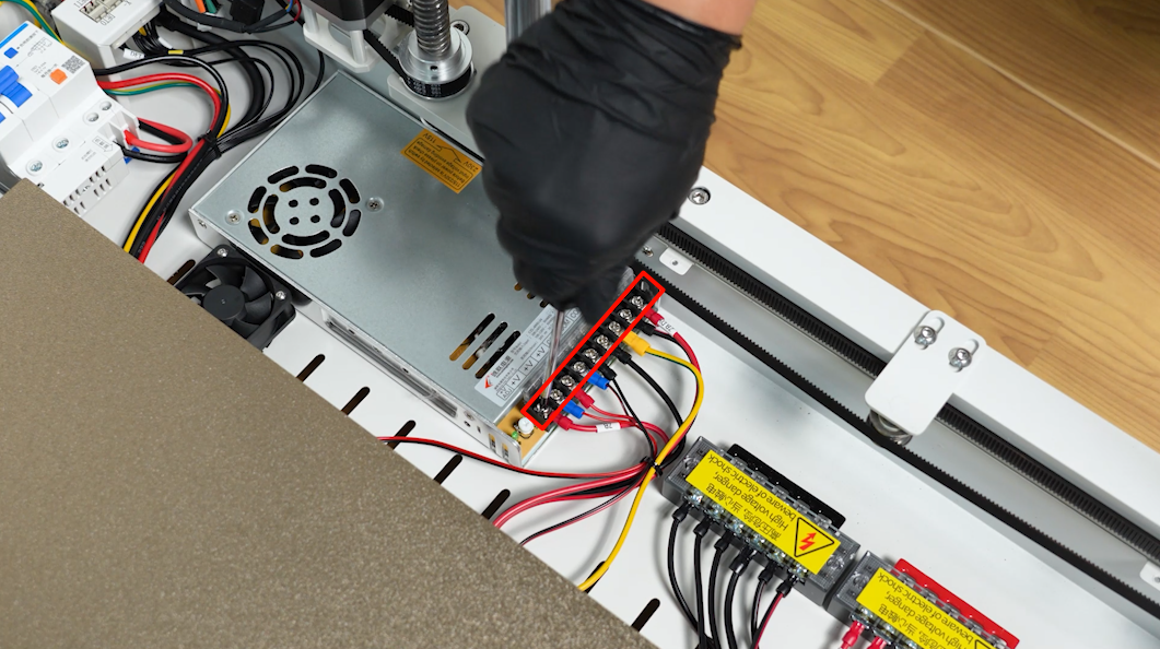
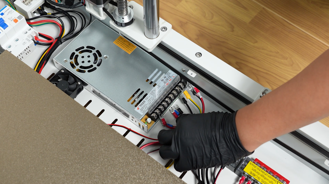
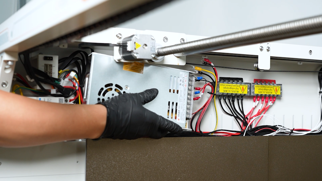
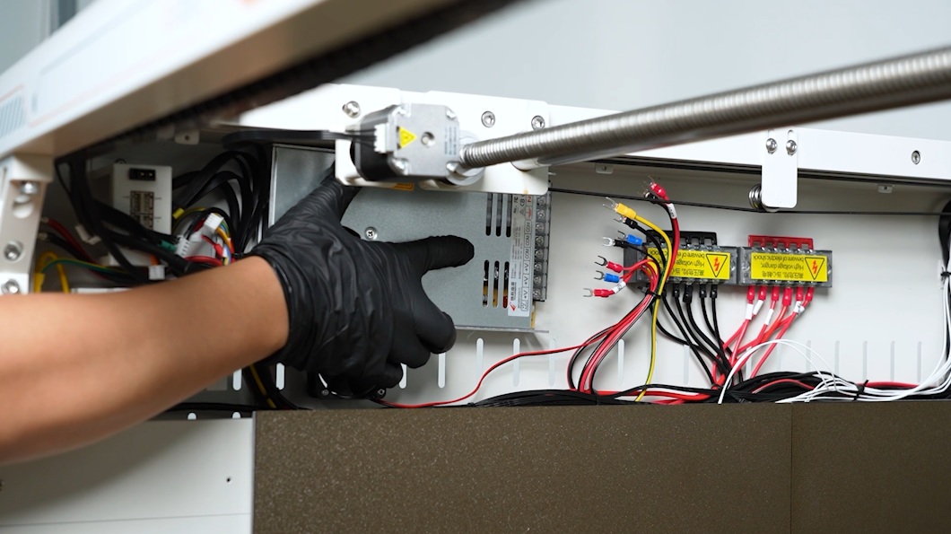
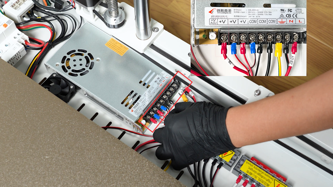
- Plug the motherboard power cable, Y-axis motor driver board cable, and cooling fan cable into the power output in order. The cathode should be coupled with the red cables and the anode with black cables. Plug the power connection cable into the power input port. The cable port labeled L should be coupled with the red live wire. The cable port labeled N should be coupled with the black neutral wire. The cable port labeled ⏚ should be coupled with the yellow ground wire.
- Put power box cover under the heated bed by placing sideways. Align the power box plate with the screw holes and slide the plate to the installation position.
- Organize the cables connected to the adapter board at the back side. Do not leave them under the plate.
- Tighten the eight screws securing the power box cover using a 2.0 mm Allen key.
NOTE: The front and rear sides are fixed with long screws and the right side is fixed with short screws.
- According to the label information, insert the cables into the adapter board at the right back side of the printer.
NOTE: Plug the cables based on screen-printing patterns.
- Tighten the two screws securing the PEI limiters at the front right side and the back side of the printer using the 2.0 mm Allen key.
- Plug in the power cord and power on the printer. Select "Prepare - All (Homing Button)" on the touchscreen.
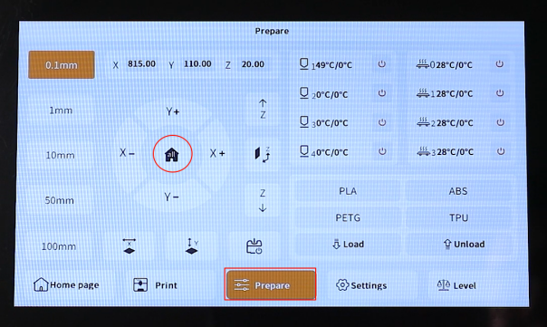
- The printer starts homing process. The printer is ready for use after the homing process.